I've taken out R14 and R15 from my circuit, and it still works fine!But it does need R16 (or R29 in the classd_fromru circuit!)
I've also made the inputs differential, and that helps a lot with stability at lower impedance loads.
The biggest problem left is if the output is short circuited without any input signal. The clock frequency almost doubles, the mark/ space ratio changes, and the negative rail 'pumps' down to about - 50V! (should be - 28V!).
Even with a differential input, the DC offset doesn't seem to be able to cope with that state.
I checked the same condition with my UcD 180, and that does exactly the same, except that the overvoltage protection cuts in, and shuts the amp off, and then 'hunts' on and off again, until the short is removed.
So the next step is to add an overvoltage protection circuit.
Then it will be both over current and over voltage protected.
Then compare the performance to my UcD 180 ??????")
I've also made the inputs differential, and that helps a lot with stability at lower impedance loads.
The biggest problem left is if the output is short circuited without any input signal. The clock frequency almost doubles, the mark/ space ratio changes, and the negative rail 'pumps' down to about - 50V! (should be - 28V!).
Even with a differential input, the DC offset doesn't seem to be able to cope with that state.
I checked the same condition with my UcD 180, and that does exactly the same, except that the overvoltage protection cuts in, and shuts the amp off, and then 'hunts' on and off again, until the short is removed.
So the next step is to add an overvoltage protection circuit.
Then it will be both over current and over voltage protected.
Then compare the performance to my UcD 180 ??????
 use IRFB52N15 (52A 150v) for high power.
Think I know how the circuit works (now ), I was just under the false impresion that people could just get this circuit to work without an od/off switch for the input section! ...... Don't thinkit is very clear from the application note either!
Think I'll just make a simple timer circuit with a single transistor.
The diode (VD8) in series withe the precharger resistor is there to prevent decharging of the upper psu is high. Don't think it is absoloutly necessary, but it will depend on things like gate drive requirement, choise of precharger resistor, psu voltae and bootstrap/chargepump capacitor size)
R14/R15 is there to increase power supply rejection ratio, which is not the best in ths kind of class-d.
), I was just under the false impresion that people could just get this circuit to work without an od/off switch for the input section! ...... Don't thinkit is very clear from the application note either!Think I'll just make a simple timer circuit with a single transistor.
The diode (VD8) in series withe the precharger resistor is there to prevent decharging of the upper psu is high. Don't think it is absoloutly necessary, but it will depend on things like gate drive requirement, choise of precharger resistor, psu voltae and bootstrap/chargepump capacitor size)
R14/R15 is there to increase power supply rejection ratio, which is not the best in ths kind of class-d.
Ok, just tryed to put in two different timing circuits, but it will not start anyway.
Pre-charger is working perfectly, and the the upper supply is charged as it should.
But it seems that the circuit needs to be tripped in some way to start.
1. I can unpug it and fast plug it in again, and it starts.
2. I can put a large signal on the input and it starts.
3. I can stop/start the current source for the input pai and it starts.
4. I can touch some of the components and it starts
Any suggestions for something very simple?
In your post #147, you mention that your circuit is configured for hysteresis rather than 'pure' UcD --- I was wondering if the extra 'gap' introduced by the hystersis requires more of a 'kick' to get it started.
With the Ucd confiuration, there is only the difference between the two comparators, and I've found they don't need to be very different to get the circuit going - the high side bootstrap pull up resistor sems to be enough.
Why have you chosen hysteresis rather than UcD modulation?
With the Ucd confiuration, there is only the difference between the two comparators, and I've found they don't need to be very different to get the circuit going - the high side bootstrap pull up resistor sems to be enough.
Why have you chosen hysteresis rather than UcD modulation?

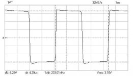
Running UcD at 233 kHz
PSU +-25VDC
It's still quite hard to get startet though
Think next step will be to implement the normal current mirror in the comparator, as Chris has pointed out a number of times, at it is running with 13 transistors in all at the moment.
Hope this might get it to start much easier. ..... might be because the gain in the comperator is too small at the moment, hvich will be increased with a current mirror, instead of the two collector resistors imployed now
PSU +-25VDC
It's still quite hard to get startet though
Think next step will be to implement the normal current mirror in the comparator, as Chris has pointed out a number of times
, at it is running with 13 transistors in all at the moment.Hope this might get it to start much easier. ..... might be because the gain in the comperator is too small at the moment, hvich will be increased with a current mirror, instead of the two collector resistors imployed now
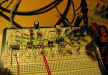
Attachments
That might be part of the problem -- breadboard circuits can introduce significant capacitance, just where you don't need it!
Maybe the breadboard layout is changing the characteristics of the phase lead network -- and making oscillation difficult to start?
Just a thought!
Maybe the breadboard layout is changing the characteristics of the phase lead network -- and making oscillation difficult to start?
Just a thought!
Imployed the current mirror, and everything works fine. no problem in starting up, when loaded.
Unloaded I sinply can't get it to start now!
At start up, there is no miss sound at all .. it just starts playing.
When cutting the power it ends in some noise.
In hysteresis mode, there is very little noise when cuting the power.
In both modes the sound seems good, but of course very har to judge on a single speaker running from a PC etc.
Next step I guess will be some PCBs. Hope to get it down to 3.3 cm x 8.0 cm ..... will make it possible to have 6 PCBs on a Euro card (10x16cm)
Made discrete UCD-klone based on Philips App note, but with all discrete components (not SMD).
Transistors are TO-92, resistors 1/4watt, mosfet BUZ31, output inductor = 30uH (17turns on barbell ferrite core).
It only oscilates at 200khz. How to make it 400khz?
In output (idle) there is sinusoidal 10Vp-p even with input is grounded. How to eliminate this?
Transistors are TO-92, resistors 1/4watt, mosfet BUZ31, output inductor = 30uH (17turns on barbell ferrite core).
It only oscilates at 200khz. How to make it 400khz?
In output (idle) there is sinusoidal 10Vp-p even with input is grounded. How to eliminate this?
lumanauw said:Made discrete UCD-klone based on Philips App note, but with all discrete components (not SMD).
Transistors are TO-92, resistors 1/4watt, mosfet BUZ31, output inductor = 30uH (17turns on barbell ferrite core).
It only oscilates at 200khz. How to make it 400khz?
In output (idle) there is sinusoidal 10Vp-p even with input is grounded. How to eliminate this?
What value of output capacitor do you use? Does the capacitor get warm? If it does, you should probably change it for some kind suited for high frequencies with lower inductance and resistance(polypropylene or similar). Also, dont forget that the output filter (LC) is second order and falls of at 24 dB/decade, and will have somewhere around half the ripple at 400kHz as opposed to 200kHz, even if 5Vp-p also is unacceptable.
The frequency of the UcD is set by tuning the feedback components to have 360 degree total open loop phase where you want oscillation, see the ucd application note for more information. This probably translates to making the feedback loop have less pahse shift at low frequencies (less C), which will shift the oscillation condition to a higher frequency.
lumanauw said:Made discrete UCD-klone based on Philips App note, but with all discrete components (not SMD).
Transistors are TO-92, resistors 1/4watt, mosfet BUZ31, output inductor = 30uH (17turns on barbell ferrite core).
It only oscilates at 200khz. How to make it 400khz?
In output (idle) there is sinusoidal 10Vp-p even with input is grounded. How to eliminate this?
Try to reduce windings count in your output inductor... But be aware
Step it down by single winding turn and measure oscillating frequency every time...Good luck! =)
zilog said:This probably translates to making the feedback loop have less pahse shift at low frequencies (less C), which will shift the oscillation condition to a higher frequency.
I have a DIY, through hole, UcD, and I have found it dificult to up the oscillation above 300KHz --- changing the values of the feedback lead network doesn't seem to make as much difference as you might expect, so I am left with the propogation delay (over which I have little control!) or the phase shift introduced by the output filter -- would it really make a significant difference to the oscillation frequency by increasing the value of the output inductor, and reducing the value of the output capacitor, in the filter?
My last UcD prototype was mostly through hole, and had no ground planes. It achieved 500-550 kHz idle oscillation.
The gate drivers were mostly SMD while most of the feedback and comparator circuitry was thru-hole, and added to that situated on a separate board away from the power board.
I sometimes observed that the oscillation frequency with no load or signal could snap between 1.1MHz and 550kHz, so I guess my control loop had some glitches.
Hi, Zilog,
At idle, there must be sinusoidal at output with frequency the same with oscilation frequency. My amp has about 1V5 p-p, this is not normal. Even before I got 10V, but I can make it down to 1V5.
I read that UCD 400 only has 20mV of this.
How many volts do you have on your DIY-UCD?
How to lower this residual carrier at output until the value only 20mV like real UCD?
- Status
- This old topic is closed. If you want to reopen this topic, contact a moderator using the "Report Post" button.
- Home
- Amplifiers
- Class D
- Philips UCD application note