diyAudio Member
Join Date: Nov 2006
I will post here because it is not 2400 post long, although the answer may be there.
Just got a gigawork up and running. It works when feeding a signal through the coaxial input but I am not having luck with the USB Port. CAN ANYONE HELP ME. Does those switches need to be changed that are on the cs4398 dac board to get sound out of the USB port????????? HELP WOULD BE APPRECIATED. Thank you in advance.
No, you don't need to change the switches on the CS4398 board. You do need to change the digital input selection jumpers though. The are on the corner of the board by the AC power inputs.
I haven't had any trouble getting USB audio to work.
No, you don't need to change the switches on the CS4398 board. You do need to change the digital input selection jumpers though. The are on the corner of the board by the AC power inputs.
I haven't had any trouble getting USB audio to work.
I have to say and am a little embarrassed that right now, I can not find that disc. Darn it. You don't suppose you could let me know where to put those jumpers to make the usb work, there are 6 pins and or jumper positions. I would count from the back of the board closest to the pins. Once again I want to thank everyone for their help. I have got to find that disc that would make this easy.
I have to say and am a little embarrassed that right now, I can not find that disc. Darn it. You don't suppose you could let me know where to put those jumpers to make the usb work, there are 6 pins and or jumper positions. I would count from the back of the board closest to the pins. Once again I want to thank everyone for their help. I have got to find that disc that would make this easy.
Mine didn't even come with the disc. The jumper positions are silk screened on the board though, so it's not too difficult to figure out.
There are really only two jumper positions that are used. There are some pull-down resistors on the bottom of the board that pull SDA SDB to 0 when you remove the jumpers.
Orient the board so the power supply section is on your right and input/output section is on your left. Now looking at the jumpers, the bottom left vertical pair needs jumpered for USB. Remove that jumper and place it on the right hand vertical pair for OPT. Remove all jumpers for COAX.
If you still have trouble, I will take a picture for you later.
I received one of these little gigawork DACs recently along with the OPA627 opamps gigawork sells. In my opinion this is a fantastic value DAC, but perhaps not a fantastic DAC. I'm undecided whether I prefer the gigawork DAC or the one built in to my Harman Kardon AVR330 (~$1k AUD HT amp). There seems to be some life missing in the music, the only thing I can put my finger on is cymbals are unable to bloom and shimmer. In time I'll do a better comparison using a better amp.
I'll eventually report back after giving it a chance to break in but suspect my hopes for $1000 sound from a $100 DAC may have been a little over-the-top.
I'll eventually report back after giving it a chance to break in but suspect my hopes for $1000 sound from a $100 DAC may have been a little over-the-top.
From what they said maybe the 11.2896 xtal osc is there as master clock source for the 1798 but in this way you can only cope with 44.1 (mclk @ 256xFs) and 88.2 (mclk @ 128xFs) and so the hint to remove it so the 1798 use the mclk generated from the receiver (cs8416) (they also said you to do some other mods to the board?).
Anyway there is something strange in this because the pcm1798 wants a master clock synchronous to the word clock and i don't understand how it is possible with a free running clock as master clock.
Ciao
Andrea
Hi,
Audiophonics said to me that the osc is used only with 44.1 Khz. others frequency use the SPDIF clock. Then I ask myself how the DAC synchonise with the SPDIF in 44.1 Khz ? the CS8416-CZ receiver gets the data its PLL synchronise with the SPDIF clock, the PCM1798 work with the OSC, and between the two chip ? buffer?
Hi robob,
i have the same doubts about this, the only thing i can say is that the cs8416 can work in slave mode (with word clock and bit clock as input and data as output) and in this mode it has a two sample buffer, but i don't see any logic block on their DAC that should do the switching from master to salve (and viceversa) and the shifting to have bit clock and word clock from master clock (the 11.2896MHz xtal osc).
Ciao
Andrea
Hi,
My source is a computer. I already tried to play files in 44.1, 48, 96 and 192KHz. the only frequency that does not give sound is the 192Khz, but nothing shows that the DAC does not always downsample all frequencys at 44.1. Is this possible ?
I have no return form the seller for the moment. Anyway this small DAC have a very good sound and if it uses his own clock at 44.1 it's a good feature to be jitter free at this frequency, no ?
Hi,
My source is a computer. I already tried to play files in 44.1, 48, 96 and 192KHz. the only frequency that does not give sound is the 192Khz, but nothing shows that the DAC does not always downsample all frequencys at 44.1. Is this possible ?
I have no return form the seller for the moment. Anyway this small DAC have a very good sound and if it uses his own clock at 44.1 it's a good feature to be jitter free at this frequency, no ?
Hi,
I say what i say only from what i see from the photos of this DAC so take this "cum grano salis".
I only see a receiver (CS8416) and a DAC (PCM1798) and no sample rate converter so i don't think it resamples anything (and this is good).
To have the master clock near the DAC is always a good thing, only i don't understand how they do the trick of synchronizing what comes from the receiver with this master clock (but maybe this is a problem due to my ignorance).
Ciao
Andrea
Hi,
Another guy on my french forum explained that (sory for my poor translation) :
This is not the DAC (PCM1798) using the frequency provided by the quartz, but the Cirrus CS8416 receiver.
It serves as a reference to the PLL integrated DAC, PLL will actually enslave the said frequency on the one taken from the SPDIF data stream.
(he only have the photos too)
In this case, the DAC does not free himself from an eventual SPDIF jitter. Or maybe the buffers are used to reduce that ?
Another guy on my french forum explained that (sory for my poor translation) :
This is not the DAC (PCM1798) using the frequency provided by the quartz, but the Cirrus CS8416 receiver.
It serves as a reference to the PLL integrated DAC, PLL will actually enslave the said frequency on the one taken from the SPDIF data stream.
(he only have the photos too
)In this case, the DAC does not free himself from an eventual SPDIF jitter. Or maybe the buffers are used to reduce that ?
Have anyone tried these transformers yet?Grael,
I'm thinking I might try your transformer mod using these less expensive transformers:
EDCOR - MXL10cs
Do you see any reason why they would not work?
You mentioned a reduction in output when going to the transformers. Have you measured the Vout? I'm afraid of it being too low to drive my amplifier.
Thanks,
Jared
MXL8cs Trans I/V
I am using the MXL8cs at 1:8 and 40R I/V resistors on each leg. They work well. A little too quiet at 40R. 1:10 and 60R maybe? The high's frequency response of the 1:10 transformer is starting to roll off but they are nice and cheap. I haven't tried the PCM1798 with opamps yet to compare vs passive
.
http://www.diyaudio.com/forums/digital-line-level/137976-experience-diy-dac-320.html#post2314483
.
http://www.diyaudio.com/forums/digital-line-level/137976-experience-diy-dac-335.html#post2344353
.
Have anyone tried these transformers yet?
I am using the MXL8cs at 1:8 and 40R I/V resistors on each leg. They work well. A little too quiet at 40R. 1:10 and 60R maybe? The high's frequency response of the 1:10 transformer is starting to roll off but they are nice and cheap. I haven't tried the PCM1798 with opamps yet to compare vs passive
.
http://www.diyaudio.com/forums/digital-line-level/137976-experience-diy-dac-320.html#post2314483
.
http://www.diyaudio.com/forums/digital-line-level/137976-experience-diy-dac-335.html#post2344353
.
diyAudio Member
Join Date: Nov 2006
I will post here because it is not 2400 post long, although the answer may be there.
Just got a gigawork up and running. It works when feeding a signal through the coaxial input but I am not having luck with the USB Port. CAN ANYONE HELP ME. Does those switches need to be changed that are on the cs4398 dac board to get sound out of the USB port????????? HELP WOULD BE APPRECIATED. Thank you in advance.
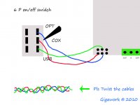
Try this switch circuit, better than fiddling with jumpers.
Attachments
Errors in filter circuit
I have been playing with one of these DACs recently and, interestingly for those who are using the OpAmp output stage, they appear to have made the same mistake to the filter components as was present in the "big" dac boards.
The filter has a bit of a "wobble" in frequency response in the HF region and, more importantly, it's not balanced meaning the common mode rejection of the balanced-to-unbalanced converter is poor, which probably doesn't help the noise performance.
Here is my post describing the filter components I used in my "Big" DAC filter. I can't see why they wouldn't work in this case (or use the circuit from the PCM1798 data sheet):
http://www.diyaudio.com/forums/digital-line-level/137976-experience-diy-dac-8.html#post1759994
Note that the I/V conversion stages are straight out of the PCM1798 data sheet and are fine.
Cheers,
kevin
I have been playing with one of these DACs recently and, interestingly for those who are using the OpAmp output stage, they appear to have made the same mistake to the filter components as was present in the "big" dac boards.
http://www.diyaudio.com/forums/digital-line-level/137976-experience-diy-dac-8.html#post1759994
Kevin,
Did they fix this on the new version of the "big" board?
Thanks,
Kevin,
Did they fix this on the new version of the "big" board?
Thanks,
I don't believe it was fixed in the "new" (with USB port) "Big" DAC that I bought in 2009. I haven't seen anything later than that I'm afraid.
kevin
Just looked in more detail at mine and it's worse than I thought. All resistors in the output filter apart from R15 and R18 were 1k ohms on mine. R15 and R18 are 1k5 (meaning there's a large DC offset at the output).
Well worth correcting these, IMHO, if you're going to use the OpAmp output.
Kevin
Well worth correcting these, IMHO, if you're going to use the OpAmp output.
Kevin
- Status
- This old topic is closed. If you want to reopen this topic, contact a moderator using the "Report Post" button.
- Home
- Source & Line
- Digital Line Level
- New Small DIY Gigawork Dac?