measure the AC voltages across pins 2 and 3, and across 5 and 6. If you don't get a clear result, do the same on the right op-amp (U12) to compare.
Thank you, Highfieldrebel, i very much appreciate your help.
I first measured wild variances, but then decided to burn a 1k tone cd from a .wav file off the web and played that into the DAC via coax.
I now measure a very steady .082v across 2/3 and 5/6 with the 100ohm resistor (probes on each leg of the resistor, not from pins to ground). My DMM reads exactly the same on both U11 and U12 on both 2/3 and 5/6.
Is that good?

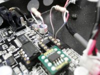
Attachments
Hi Mootzeroni
this sounds like good news and a very good idea about the single tone CD. I suggest you follow the schematic through, check the o/p of the two I/V op-amps versus ground. If that's ok (i.e. the same for all four outputs) move onto the inputs and then the outputs of the last op-amp stage. If they're ok, onto the switch U10. I don't understand the function of this IC, I must admit. If you get this far though without finding the fault, I think you are in good shape. If the switch is fried, I think you can just route around it. Of course if anyone else can tell us the function of U10 I may have to revise that opinion.
S
U10 is just a mute chip.
When there is no spdif signal (blue led not lit), the pcm1798 outputs some "noise", white noise or something, and the U10 is there to cut the output.
So it is not critical.
If your two i/v sockets are good, as it seems to be, then go ahead and try output transformers or lampizator!
When there is no spdif signal (blue led not lit), the pcm1798 outputs some "noise", white noise or something, and the U10 is there to cut the output.
So it is not critical.
If your two i/v sockets are good, as it seems to be, then go ahead and try output transformers or lampizator!
Last edited:
Dear Highfieldrebel and Grael (et al)-
I messed up. After tracing things down (per your helpful suggestions), everything up to the final opamp sockets seemed fine... what happened was i had loose socket holes resulting from stuffing the fatter Burson op amp legs in, then removing it to substitute another to try to diagnose the gain distortion i was getting. I flipped and fried the substitute, then was afraid to put the (expensive) Burson back in so i was using regular skinny-legged dual opamps which didn't make contact on the Rt channel legs. Oy vey. All is fine now with the Burson back in, thankfully. Doh!
I still have what i believe to be too hot an output level for my preamp, resulting in that familiar over-driven distortion clipping on louder musical passages, like you'd hear if you pegged the meters on your old cassette deck. Is there a way to attenuate the signal somewhere before or after the Burson to make my preamp happy? With my ripped 1k tone which shows +3db in DAW (LogicPro), i measure 1.45v Left and 1.43v on the Right outputs. I get about half that on most CDs, but say on louder passages of Regina Spector's "Begin to Hope" I hear distortion on loud passages and DMM reads over 1.0volts during those. That's too much output, no?
Thanks in advance.
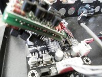
Attachments
Hi Mootzeroni
that's excellent news, and I'm amazed at the size of the Burson. If you press ahead with transformer outs, you can compare the two. A quick look at ebay suggests they're similarly priced?
The analogue chain now has two op-amps in series, is it helpful to upgrade one rather than the other?
Re your saturation issue, I'm using the DAC instead of a preamp, I'm doing source selection on the digital side and I have a stereo pot between the DAC out and power amp in. This leaves me with an unresolved remote control issue, but that's for another day's bodging. If you will retain your pre-amp, I don't see an issue with putting a resistor divider in the DAC box ........ does anyone know better?
Hi Mootzeroni
excellent news, and I'm amazed at the size of the Burson.
It's a little exaggerated in the photo due to a wide macro with Burson only about an inch from the lens. It is rather large, optics notwithstanding.

Gentlemen,
I'm soon to purchase a dac. I've been watching here a while. I have the opportunity to purchase an Adcom GDA 700. I need help with the decision.
I have built speakers, amps and x-overs. This would be my first digital effort. I feel that I could invest as much in the Adcom as the Gigawork and not have a better unit.
So, I ask your opinion on the above.
Re your saturation issue, I'm using the DAC instead of a preamp, I'm doing source selection on the digital side and I have a stereo pot between the DAC out and power amp in. This leaves me with an unresolved remote control issue, but that's for another day's bodging. If you will retain your pre-amp, I don't see an issue with putting a resistor divider in the DAC box ........ does anyone know better?
I tried simply adding a 100ohm resistors as a shunt(?) between the RCA terminals, hot and ground, right at the back of the RCA connector. This has reduced the distortion on the loud passages dramatically. Is this bad for the DAC or expensive op amps? Is there a better way, like biasing the op amps? Should i use a series and shunt to ground instead? My integrated amp has 47ohm impedance, fwiw.
Forgot Ohm's law like 30 years ago.

Hi Mootzeroni
I think the input impedance of your amp is more likely 47 kOhm.
What I think is happening is that you are drawing so much current with the 100 Ohm load, that a significant amount of the DAC voltage is developed internally, and you are getting a voltage drop. This is not a good way to go, it guarantees distortion as the op-amp circuit output impedance will not be flat with frequency.
I suggest this: make a resistor divider with two large resistors, say 47 kOhm and 10 kOhm. Solder them together, put the free end of the 47 kOhm resistor to the DAC output, put the free end of the 10 kOhm resistor to the RCA ground, put the junction of the two resistors to the RCA centre conductor. The output voltage should drop by (10/(10+47)).
I should comment I am no expert on this stuff, but this is how my potentiometer is working, the two resistors just won't be adjustable.
Hi Mootzeroni
I think the input impedance of your amp is more likely 47 kOhm.
What I think is happening is that you are drawing so much current with the 100 Ohm load, that a significant amount of the DAC voltage is developed internally, and you are getting a voltage drop. This is not a good way to go, it guarantees distortion as the op-amp circuit output impedance will not be flat with frequency.
I suggest this: make a resistor divider with two large resistors, say 47 kOhm and 10 kOhm. Solder them together, put the free end of the 47 kOhm resistor to the DAC output, put the free end of the 10 kOhm resistor to the RCA ground, put the junction of the two resistors to the RCA centre conductor. The output voltage should drop by (10/(10+47)).
I should comment I am no expert on this stuff, but this is how my potentiometer is working, the two resistors just won't be adjustable.
Ah, i get it... I think i saw this elsewhere...
http://www.diyaudio.com/forums/parts/90918-diy-line-attenuator.html
and as a product:
Attenuators
so the 47k resistor is in series and the 10k goes from the signal to ground (and same for the other channel). I just tried it with lower values (1.5k and 220ohm) and there is less distortion on the louder passages... i'll try larger values. Will 1/4watt resistors suffice? THANK YOU!!!
Attachments
P = U²/RWill 1/4watt resistors suffice? THANK YOU!!!
So, if U=4V (more than real value), 1/4 watt are ok with R>64 Ohm.
You're safe with 1/4 watt.
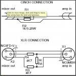
ideal resistor divider
Hi Mootzeroni
apologies, I lost the thread updates...
I've attached a sketch of an ideal divider (I hope it comes out, I've not tried this before)
Anyway, imagine a Vin (the output of the DAC) driving a current i through two resistors, i=Vin/(R1+R2). Then approximate that no current leaves the line Vout. This is nearly true if R2<< whatever we connect at Vout (your power amp), might be the case. The voltage across R2, which is Vout=R2*i, from before this makes Vout=R2*Vin/(R1+R2).
And that's it in the ideal case, more careful consideration will bring into the equation the capacitance of the cables, but let's not worry about this today.
To reply directly to your post: the 47k and the 10k are in series from the DAC output to ground. The 10k lies between RCA output and ground. And as Grael pointed out, power rating of the resistors is not a problem. Can't see a smilie that represents crossing your fingers the pdf comes through...
Attachments
very cool, thx.
Comes through fine and thank you VERY much. Now I've learned something (which i can't really say of the balance of the day until now)
I'll try it in the morning after café.
Thanks again.
Hi Mootzeroni
I've attached a sketch of an ideal divider (I hope it comes out, I've not tried this before)
Can't see a smilie that represents crossing your fingers the pdf comes through...
Comes through fine and thank you VERY much. Now I've learned something (which i can't really say of the balance of the day until now)
I'll try it in the morning after café.
Thanks again.
I dont know about that. the spec shows only a few db difference in dynamic range 123db vs 127 dB with very similar noise performance THD+N: 0.0005% vs 0.0004% and a lower current output (to be expected with a device designed for lower power consumption) and the sound signature is about the same IME, where changing opamps can actually change the flavor.
so I dont know where your VERY BIG IMPROVEMENT is, could it be an exageration? have you actually compared both devices?
so I dont know where your VERY BIG IMPROVEMENT is, could it be an exageration? have you actually compared both devices?
It's a simple fact that the 1794 is going to sonically outperform the 1798. It is a better DAC. Kind of a no-brainer upgrade to me, at least.
Remember, garbage in, garbage out. While I'm not saying the 98 is garbage, I am saying this: starting with the highest quality source you can generally leads to the best sound. The output stage is merely a supporting part that must be good enough to allow the best sound from the DAC chip through.
Higher spec DAC = truly higher fidelity instead of a new "flavor" of a lower spec DAC.
As a side note, I would get rid of the op-amp output stage altogether, and implement a discrete transistor, tube, or transformer gain stage with a resistor I/V.
I dont object to the statement that it SHOULD perform better, it does perform better and the numbers prove that. what I object to is the patently ridiculous statement that it would produce a 'VERY BIG IMPROVEMENT' when even the spec sheet doesnt indicate this; let alone my ears, which have actually heard and own both dacs in the same design (the TP COD, not this dac) I built one with both chips. it sounds like you havent heard either, let alone done a test between both in the same design.
your claim to be able to clearly hear a very big difference of 3db is weird, but mainly it isnt even the point. generally people change opamps in a kit like this to get a different sound signature, not so much to gain a few DB noise performance. most modern opamps measure about the same and would sound about the same if all were installed a circuit that meant each was performing at its best. but because the chips all prefer slightly different compensation, slightly different supply voltages etc, each tends to sound a little different.
I prefer simple discrete SS circuits as well, but that isnt the point here now is it?
Last edited:
also, replacing a dac chip on what is a pretty cheap PCB isnt what I would call a trivial operation, let alone for someone who bought it to roll a few opamps. with the right equipment its a pretty simple operation, but with a standard soldering iron heating both sides of the chip so you can lift/flick it off without lifting a pad is a risky operation
let's re-read my original statement, because for some reason you think i'm trying to sell you something: "I would imagine it would be a very big improvement". Obviously, this is speculation.
I would still change to the higher spec DAC first, however. It's not hard if you have a heat gun and a flux pen.
I would still change to the higher spec DAC first, however. It's not hard if you have a heat gun and a flux pen.
- Status
- This old topic is closed. If you want to reopen this topic, contact a moderator using the "Report Post" button.
- Home
- Source & Line
- Digital Line Level
- New Small DIY Gigawork Dac?