Hi,
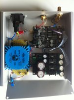
I am a happy user of this kit (see mine in the attached picture). I modified the original kit by changing the original AD op-amps with LM4562. The only singular behavior, compared with the other dac I have (DAC 707 Superpro), is the higher output level of signal also reported by other people in this thread. I am using the coaxial PSDIF input connected asyncrhonous to a Mac via a M2tech usb interface.
However, since I switched to a chip amp I noted that the chip-amp was getting very warm even without playing music (not with the other dac or CD player I have). Then I measured at the new Gigawork dac 750mV DC at signal out when the dac is connected to the Mac on both channels. If the dac is disconnected from the Mac I measure 2mV.
Connected to the Mac, the Superpro dac gives 9mV out.
I can hear a very high hum noise from the speakers when the amp volume is at maximum level.
Is there something wrong?
Thank you for your feedback
Renato
Attachments
I plan to buy this DAC but wonder how it compares to a decent soundcard like Asus Xonar DX or other of the same price/quality. Did any of you have the chance to compare them?
Sounds very good if you rebuild the analogic part on a separate (new) board. The included I\U and buffer are built with wrong components and is almost imposible to change the smd resistors/capacitors.
board resistor components!
I have to agree with Atupi, i own 2 of these DAC boards and both of them have components around the I/V an buffer stage with incorrect component values!
In my case even the two boards have both wrong component values but there are also differences between the two boards.
I use a seperate I/V stage to overcome these problems.
Hi,
with reference to my post #245, I solved my problem by inserting an AC couplig cap at output (my amplifier is a DC coupled chipamp). Unlikely, I did not believe how much important was the influence of a cap on the audio signal: the cap added a veil to the music.
There is not sufficient space in the chassis to put a polypropilene cap, so I used a an electrolytic 4.7microF/35V Rubycon ZA.
Have you a suggestion for a better choice (forgetting BG N that I cannot find)?
Thank you
Renato
Hi northernsky,
I think i am having the sane issue.
I removed the multiplexer mute chip.
I Also added the four 470 ohms to reduce output voltage.
I realized one of my amps didn't work.
So I tried a little SEP amp with capacitors at it's inputs and it sounded well.
So I am guessing I have the same DC problem.
Now I am adding 2 PIO .33 UF caps to test with my main amp and see how it goes.
Even with this work arround, there should be a cleaner way of fixing this issue?
I am afraid of those bypass caps ruining the sound..
Cheers
Listening to the new setup now.
It sounds well, distortion seems to have dissapered.
I don't have a pre, just volume on a Mac.
My speakers are super sensitive so I guess I will adjust again those opamp resistors to reduce opamp gain a little more.
What makes me happy about this setup is that I am not noticing a high frequency roll-off as when using a potentiometer before the power amp Push Pull el84.
But even when my system performace has improved
Is a coupling CAP between dac and power ideal?
I guess, a less component approach is aleáis better when possible.
Ideas to remove opamp stage bias:
1) test upgrade opamp power supply?
2) matching resistors in opamp section?
3) or just use a very boutique cap ?
Thanks
Is a coupling CAP between dac and power ideal?
I guess, a less component approach is aleáis better when possible.
Ideas to remove opamp stage bias:
1) test upgrade opamp power supply?
2) matching resistors in opamp section?
3) or just use a very boutique cap ?
Thanks
- Status
- This old topic is closed. If you want to reopen this topic, contact a moderator using the "Report Post" button.
- Home
- Source & Line
- Digital Line Level
- New Small DIY Gigawork Dac?