Hi Gareth,
This is a journey you are taking. Once you have this working to your satisfaction, try these other various ideas out to see what effect they have on performance and sound quality. Use that THD meter and also look at the residuals with your 'scope. You will learn a fair amount by doing this.
-Chris
There are times when you may need more than one active stage to get the job done. This will depend on your specific situation, but with an insensitive output stage, you may want to consider adding another stage there. Running a tube stage wide open places too much dependence on the actual tube for the character of sound. Local feedback normally will stabilize the operating point better and also make the circuit less sensitive to the character of each individual tube.I'm using a choke load to maximize the gain from the input tube which has a maximum rated mu of 20
That's fine, and no problem there. Read up on leakage inductance and distributed capacitance in transformers and chokes. I can't say much without testing that choke, but your drop off in HF response in the input stage suggests more than Mr. Miller at work.The choke does restrict bass extension but I'm measuring an actual -3dB of 30Hz from the input tube which I'm happy with.
Try a positive bias later on then. This is an excellent tool for reducing heater induced hum.I've returned the heater bias C.T. to ground.
Thank you. I haven't gone through all my messages yet, but I'll look for this one.I'll attach it to this post and also ping you an email copy.
Okay - good. This is something to keep in the back of your head whenever you are working with high voltages. In case you are restoring a piece of equipment, you will know why there is a string of series resistors instead of one or two. I've seen cases where a "tech" used one equivalent value for all the string. Guess what? The unit ran for a bit and finally failed. That tech couldn't find the problem either, so I got it later in the process.Currently, I'm not exposing any resistors to a high voltage, the worse case is the cathode bypass resistor at 70V
Gareth, early tube type equipment did use selenium rectifier stacks for this purpose. In my view, SS diodes are a reasonable and authentic device to use, and for exactly this reason. It's your build, but there is no reason to exclude diodes.I'd have to introduce another rectifier and since no SS is allowed that means another tube and more load on the heater supply.
I know why Hugh doesn't care for these, but it's possible that poorly performing CCS circuits are the reason you heard other comments. A properly designed CCS circuit will drop the distortion of most gain stages. Also, a CCS shields the gain stage from power supply noise. As an emitter (or source) load in a follower, improvements in distortion are common as well. Also keep in mind that popular opinion often follows audio lore rather than personal experience. Another factor when looking at audio circuit ideas.Having read such opinions I never made any of my SS amps with a CCS load on the input.
This is a journey you are taking. Once you have this working to your satisfaction, try these other various ideas out to see what effect they have on performance and sound quality. Use that THD meter and also look at the residuals with your 'scope. You will learn a fair amount by doing this.
-Chris
Do you see those four empty bolt holes in the core?
Thanks for the advice! But where would I get those bolts? The originals were very soft and easy to wreck, even with the right size screwdriver. I had to cut one off.
- keantoken
Member
Joined 2009
Paid Member
Hey,
Get rid of those SS diodes you have more than 2V input they will clip your signals before it reached the tube.
Have fun
SS
This is the protective earth, separating the audio ground from chasis ground but ensuring a safe path for current in the event of a failure. It's connected to the gnd of the signal not the signal it'self.
Hi Bigun,
I normally see a resistor across the diodes as well. The diodes prevent the resistors from burning out when the ground current is too high. 100R would be a good value, possibly with a two diode drop setup, pair 'o zener diodes maybe? You only need to protect the resistor. This would reduce circulating ground current and avoid just having common peaks causing current flow. Diodes begin conducting around 0.4 V, then the impedance drops down pretty low as current goes up.
-Chris
Member
Joined 2009
Paid Member
Member
Joined 2009
Paid Member
I've been distracted, vacations and other stuff. Well my tube benefactor furnished me with some copper tape which allowed me to put some belly straps on all the trafo's (see attached - although OTs not shown they were also strapped).
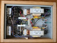
I'm going to have to rewire this thing, it's a mess. I have relocated the on/off to the back and use the hole left behind to install an Alps pot for a volume control. Now that the cooler nights are on their way, finishing this thing off will give me a private heater
photo credit goes to my ankle biters - they wanted to 'help' so I gave them a project, one was the photographer, the other was the artistic director.
Attachments
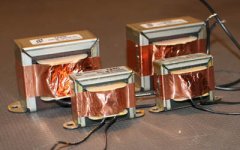
photo credit goes to my ankle biters - they wanted to 'help' so I gave them a project, one was the photographer, the other was the artistic director.
At least, finally they had some toys to play with.
Member
Joined 2009
Paid Member
Member
Joined 2009
Paid Member
Member
Joined 2009
Paid Member
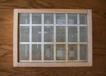
Well it was time to rip out the wiring and re-do it in order to make any progress. It was working but it was never going to fit inside the box properly. Put it down to beginners learning. I've added the Alps volume control and installed some new Russian PIO inter-stage coupling caps. I don't know how well the thermal management is going to work out yet, the cathode bypass resistors are held up in 'open space' away from other components and I've added ventilation holes around the power tube to help air flow inside the chasis.
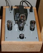
However, I wasn't able to make it super neat or to a standard that I'd be happy with if it wasn't my first tube amp but I learned a lot that will make the next one all the better.
It's now playing in my living room, through my DIY Moon Onken speakers. I not only hear the violins, I hear the bow on the strings. Nice.
A couple of photos attached, the underside open, the underside with a safety cover and the top side. It still needs proper feet.
Attachments
Hi Gareth,
Looks pretty nice. Not only that, but it's finished and working.
Hey Gareth, I've been looking for that copper tape for over a year. Is there a place that sells it anywhere around here? I'm also looking for some small bar stock, about 3/87" square or slightly larger. I can cut the bar into small bits in order to use them for tying diff pairs together.
Sorry for the O.T.
-Chris
Member
Joined 2009
Paid Member
I've been looking for that copper tape for over a year. Is there a place that sells it anywhere around here?
this is where mine came from (Toronto)
A1 Electronic Parts - Serving the Toronto area for 30 years!
I'm also looking for some small bar stock, about 3/87" square or slightly larger. I can cut the bar into small bits in order to use them for tying diff pairs together.
try searching the internet for 'Metal Depot'
glad to be of help !
Member
Joined 2009
Paid Member
Well I've had a couple of evenings to sit quietly and listen using my Magnum Dynalab FM tuner, CELLINI and Moon Onken speakers.
I'm completely sold on tubes. I've simply never heard an amp sound like this. Voices and percussion sound as if they are real, right here in the room with me.
I never knew what I was missing. Wow.
Hopefully it'll wear off or I'll struggle to justify doing another audio project.
I'm completely sold on tubes. I've simply never heard an amp sound like this. Voices and percussion sound as if they are real, right here in the room with me.
I never knew what I was missing. Wow.
Hopefully it'll wear off or I'll struggle to justify doing another audio project.
- Status
- This old topic is closed. If you want to reopen this topic, contact a moderator using the "Report Post" button.
- Home
- Amplifiers
- Tubes / Valves
- my CELLINI triode amp