And that's with the 6AS7 which 99% of those other tube freaks claim is a bad tube")
Wait until he hears the 2A3/45, then wait for him to tell you how much time it took him to dump your lovely 6AS7's. To be continued.
my little secret
LOL, everybody has tried to save a few bucks with that cheap tube.
Member
Joined 2009
Paid Member
I'm sure there's more to tube amps than the first one I've built, but my experience is a vote in support of the 6AS7 driven by a choke loaded 6SN7 (well actually it's the Russian equivalents to these tubes that I'm using).
I'll keep reading and learning, but I've never felt drawn to use the boutique tubes (2A3, 300B) just because they are so hyped but I believe many of these tubes (incl. 6AS7) are related by history ... I now have ten NOS russian 6C4C's should the urge to build again take root
I'll keep reading and learning, but I've never felt drawn to use the boutique tubes (2A3, 300B) just because they are so hyped but I believe many of these tubes (incl. 6AS7) are related by history ... I now have ten NOS russian 6C4C's should the urge to build again take root
Last edited:
Hi SemperFi,
There are plenty of tubes that will work well in various circuits. I think the TV horizontal sweep tubes are popular and you can get really high power from them. Many commercial PA amps in the 60's used sweep tubes, including Bogen. They sounded extremely good too.
Hi Gareth,
Those 6C4's make very good signal amplifiers. I have seen them used as rectifiers and low power outputs. Such treatment for what was designed as a high frequency oscillator tube! Hang on to them.
As for your Russian tubes, try to get the actual Russian specs for them and adjust the North American circuits for these. There is a slight difference and performance can be improved by doing this. Note that the circuits will work if you don't adjust anything. Just not as well.
-Chris
I have a Lambda power supply that needs 6 of those. They died all together in one go, it was pretty nasty.I've got some 6W6 waiting to be in my next SE amp.
There are plenty of tubes that will work well in various circuits. I think the TV horizontal sweep tubes are popular and you can get really high power from them. Many commercial PA amps in the 60's used sweep tubes, including Bogen. They sounded extremely good too.
Hi Gareth,
Those 6C4's make very good signal amplifiers. I have seen them used as rectifiers and low power outputs. Such treatment for what was designed as a high frequency oscillator tube! Hang on to them.
As for your Russian tubes, try to get the actual Russian specs for them and adjust the North American circuits for these. There is a slight difference and performance can be improved by doing this. Note that the circuits will work if you don't adjust anything. Just not as well.
-Chris
Member
Joined 2009
Paid Member
I normally see a resistor across the diodes as well.
A resistor ( I had one lying around
) has been installed...Attachments
Hey Bigun, congrats! I still have yet to get my tube receiver working.
What confuses me is that with all the SS circuitry in the source processing, the fact that a tube amp makes it all okay suggests that there is some specific flaw in SS amps which can be corrected. Thoughts?
When possible, I want to send you a prototype of my headphone amp and get your opinion. Are you game?
- keantoken
Hi Gareth,
That should do the trick. I look at those diodes as a way to limit the dissipation of the resistor. So a lower value might work fine there. I don't think you need to change it now, that circuit is not critical as far as part values are concerned.
-Chris
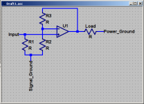
The amp compares two signals:
1: The input voltage to ground voltage.
2: The output voltage to ground voltage.
3: The difference between the first two comparisons.
Separating signal and power grounds totally splits these:
1: Input voltage to signal ground voltage.
2: Output voltage to signal ground voltage.
3: Difference of first two comparisons.
By this we see that power ground is no longer being factored into the comparison, and since power ground is the negative terminal for the speaker, any fluctuations in power ground will be added to the output signal.
For this reason I don't think complete separation of grounds is a good idea.
Am I right?
- keantoken
Hi keantoken,
The audio system "ground" (common may be a better term here) and the outside chassis safety ground (that is returned to ground potential) are often coupled by resistance. You only need enough to break any ground loops (reduce the circulating currents between two or more audio components). A total disconnection between grounds shouldn't affect the operation of the amplifier except for possibly radiating noise into the circuits.
Let's revisit your opening statement:
Statement 2. is not true. An amplifier amplifies the difference between whatever appears between it's inverting and non-inverting inputs (just like an op amp). In the first case I was talking about the actual input device, but if you apply the same principles, the feedback signal travels through the opposite device and is presented to the input device through the emitter connection. Still works.
Statement 3. Well, loosely kinda sort of maybe. The feedback signal from the output is divided down by the feedback network. This reduced signal is applied to one input point and the input signal is applied to the other. Since the input device is set up to amplify the difference between these two signals, only this difference is amplified. There is no interim comparisons made at all, just a level reduction (without which the voltage gain would be 1, or 0 dB).
-Chris
No, the speaker return is not connected directly to the chassis.and since power ground is the negative terminal for the speaker, any fluctuations in power ground will be added to the output signal.
The audio system "ground" (common may be a better term here) and the outside chassis safety ground (that is returned to ground potential) are often coupled by resistance. You only need enough to break any ground loops (reduce the circulating currents between two or more audio components). A total disconnection between grounds shouldn't affect the operation of the amplifier except for possibly radiating noise into the circuits.
Let's revisit your opening statement:
Statement 1. is almost true. The first stage of an amplifier amplifies the difference between it's common reference point (signal common) and the first amplifying device. For instance, in a tube amplifier, the input tube amplifies whatever appears between the grid and cathode of that tube. A solid state amp will amplify whatever appears between the base (gate) and emitter (source) of the first transistor. An op amp amplifies whatever appears between the inverting and non-inverting inputs.The amp compares two signals:
1: The input voltage to ground voltage.
2: The output voltage to ground voltage.
3: The difference between the first two comparisons.
Statement 2. is not true. An amplifier amplifies the difference between whatever appears between it's inverting and non-inverting inputs (just like an op amp). In the first case I was talking about the actual input device, but if you apply the same principles, the feedback signal travels through the opposite device and is presented to the input device through the emitter connection. Still works.
Statement 3. Well, loosely kinda sort of maybe. The feedback signal from the output is divided down by the feedback network. This reduced signal is applied to one input point and the input signal is applied to the other. Since the input device is set up to amplify the difference between these two signals, only this difference is amplified. There is no interim comparisons made at all, just a level reduction (without which the voltage gain would be 1, or 0 dB).
-Chris
The way I see it, every signal has two components, a reference and data wire. A receiving device compares the difference between the reference and data, and variations of both are ignored. When we measure output voltage, we must measure it against a reference, most commonly power ground. If we break signal and power ground, the signal ground becomes the reference for the entire amplifier. So if your source's ground increases by 1V, so will your output voltage, because power ground will not follow the signal ground voltage. Not only this, but power pulled from rails and into the load will force ground up or down, increasing supply-related distortions.
Am I still wrong?
- keantoken
Am I still wrong?
- keantoken
If we break signal and power ground
If you do that, how will the power supply supply power to the amp? Are you confusing 'power ground' with 'mains earth'?
So if your source's ground increases by 1V
Compared to what, power ground or mains earth?
Am I still wrong?
I'm afraid so. Disconnecting signal ground and power ground causes the amp to stop functioning. Disconnecting signal ground and mains earth doesn't change anything to the operation of the amp (unless there are ground loop faults or so)
Here is what I'm imagining.
Whenever I mention breaking signal and power ground, I imagine a perfect world where input bias currents, offsets and DC don't exist. I speak in terms of the two extremes, totally separate power and signal grounds and totally connected grounds, because this simplifies the explanation as well as highlighting the fundamental differences between the two.
It is obviously not practical to separate signal and power grounds entirely.
- keantoken
Attachments
The way I see it, every signal has two components, a reference and data wire. Am I still wrong?
Optical S/PDIF, FM Radio, groove in a record. Analog tracks on film and tape.
Spring in a reverb tank. List goes on and on.... Show me the reference wire?
Last edited:
Optical S/PDIF, FM Radio, groove in a record. Analog tracks on film and tape.
Spring in a reverb tank. List goes on and on.... Show me the reference wire?
Optical/digital - 0 or Off reference
FM - unmodulated carrier reference
Record groove - the position of the tonearm
Tape - unmagnetized ferrite
A signal means nothing to us if we can't compare it against another value. If our tonearm on our record was vibrating to an arbitrary waveform, would it's output be recognizable? Same for FM, if our carrier is is shooting up and down the spectrum, can we tell what's the signal and what's not?
There are two components of a signal - the reference and the data. The reference is the same as the signal, minus the signal. Comparing the difference between these two gives you the signal and nothing else.
The reference is often DC whereas the signal is AC, but this isn't necessary, it is only convenient and simpler and tolerates bad equipment.
- keantoken
Member
Joined 2009
Paid Member
Hey Bigun, congrats! I still have yet to get my tube receiver working.
What confuses me is that with all the SS circuitry in the source processing, the fact that a tube amp makes it all okay suggests that there is some specific flaw in SS amps which can be corrected. Thoughts?
When possible, I want to send you a prototype of my headphone amp and get your opinion. Are you game?
- keantoken
Thanks Keantoken for the good words on the amp. I'd be interested to hear more about your receiver (PM me) as I have one too !
The question about the source is a bang on the money. I don't plan to look at making a better amp than Cellini without considering the whole audio chain because the source maybe the weak link. But broadly speaking, what I gather from reading so far, there are key points in the chain where tube amps are believed to offer a benefit - and these points are where the electronics interface with the real world - transducers (the microphone/pick-up/speaker). It's a topic I'm not very knowledgeable of and probably deserves a separate thread to cover it properly.
In terms of there being a specific flaw in SS amps - I'd suggest this is not the way to think about it. I'd suggest that different amplifiers with their respective topologies, types of active devices, construction details and operating points each have their own pro's and con's and the skill of the designer shines through in how he/she makes all the relevant choices.
I'd be honoured to try out your headphone amp ! - but I don't have any high quality headphones. I may be able to borrow a pair, I'd have to ask around.
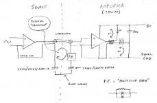
In terms of the questions over signal ground / chasis ground - see attached drawing. I try to analyze circuits from two viewpoints - 1) it's all about current flow and current flows in loops, and 2) all active devices are voltage controlled where the control voltage is a potential difference between two control inputs. I've represented an amplifier as a device with two control inputs as you suggest.
In the attached plot we see the 'system' and the reason for the resistor + back to back diodes to form a 'protective earth' (PE). The PE ensures that there is a path for dangerous currents to flow to safety earth in case of a fault whilst presenting a non-zero impedance to a.c. signals flowing through the ground connections due to induction in 'ground loops'. What I see from this is the need to ensure the impedance of the PE is linear or we have the potential to create unwanted noise currents that can produce voltage differences where they are not wanted (i.e. eventually at the input to active devices).
Now it's my turn to ask if I'm wrong or right ? (or have even understood the question!)
Attachments
Last edited:
Hi keantoken,
In your diagram, you show the speaker return and the signal common totally separated. That will never work, although a tube amp can get close if it has no feedback from the output. Thats because the speaker load can have it's own little unreferenced loop, just it and one winding on a transformer. If you add feedback, you must reference the output winding to common as you are using a signal to allow correction. All signals must have a reference to something, somewhere. Hopefully a nice quiet one without much COMMON MODE NOISE. There's a hint back there that is the root cause of the ground isolation device Gareth made. Can you find it?
Now, to examine your examples:
Optical output, there's a good thought exercise! You are measuring the presence or absence of energy. The reference isn't like an electrical signal where you have a physical reference. Perhaps this kind of reference does exist, but we haven't discovered it's existence yet. Once it's converted to an electrical signal, we do have a reference. Work is being done on light signaling in microprocessors as we speak though.
The reference for any electromagnetic wave (like any radio wave) is earth ground. The energy sent out returns to the transmitter via the ground. In aircraft or satellites, the ground is an artificial one, and it is the chassis. They are designed that way or they wouldn't work.
Record. The reference there is in the cartridge. In the magnetic style, one end of the coil is signal and the other is reference. Of course, that's artificial because a cartridge is a balanced device. The groove simply supplies the motion to excite the stylus in order to create the signal. The reference is the mean center of motion if you want to look at it that way. We only hear the changes from center (or the rest position).
Tape. Much like a record groove. When recording the reference is one side of the recording head gap. In playback the reference becomes one side of the gap in the playback head. The heads (both types) are balanced devices, although Nakamichi produced a special center-tapped head in their top models for automatic azimuth correction. Cool concept and it works extremely well.
Hi Gareth,
Actually, the impedance only needs to be high enough to limit the induced current to a low level below other forms of noise. With a zero ohm connection, the induced currents can be much higher, causing trouble as it is induced (transformer action) into other conductors. If the current is reduced by raising the impedance, you will have a greatly reduced electromagnetic field radiating from the "ground" connections. By including the diodes, you are still protected from line faults if they should occur.
-Chris
In your diagram, you show the speaker return and the signal common totally separated. That will never work, although a tube amp can get close if it has no feedback from the output. Thats because the speaker load can have it's own little unreferenced loop, just it and one winding on a transformer. If you add feedback, you must reference the output winding to common as you are using a signal to allow correction. All signals must have a reference to something, somewhere. Hopefully a nice quiet one without much COMMON MODE NOISE. There's a hint back there that is the root cause of the ground isolation device Gareth made. Can you find it?
Now, to examine your examples:
Optical/digital - 0 or Off reference
FM - unmodulated carrier reference
Record groove - the position of the tonearm
Tape - unmagnetized ferrite
Optical output, there's a good thought exercise! You are measuring the presence or absence of energy. The reference isn't like an electrical signal where you have a physical reference. Perhaps this kind of reference does exist, but we haven't discovered it's existence yet. Once it's converted to an electrical signal, we do have a reference. Work is being done on light signaling in microprocessors as we speak though.
The reference for any electromagnetic wave (like any radio wave) is earth ground. The energy sent out returns to the transmitter via the ground. In aircraft or satellites, the ground is an artificial one, and it is the chassis. They are designed that way or they wouldn't work.
Record. The reference there is in the cartridge. In the magnetic style, one end of the coil is signal and the other is reference. Of course, that's artificial because a cartridge is a balanced device. The groove simply supplies the motion to excite the stylus in order to create the signal. The reference is the mean center of motion if you want to look at it that way. We only hear the changes from center (or the rest position).
Tape. Much like a record groove. When recording the reference is one side of the recording head gap. In playback the reference becomes one side of the gap in the playback head. The heads (both types) are balanced devices, although Nakamichi produced a special center-tapped head in their top models for automatic azimuth correction. Cool concept and it works extremely well.
Actually, not always. It depends. In many cases, the reference may have a signal (unwanted) on it. The use of balanced signals help to minimize this "noise" by making it "common mode".The reference is often DC whereas the signal is AC, but this isn't necessary, it is only convenient and simpler and tolerates bad equipment.
Hi Gareth,
Actually, the impedance only needs to be high enough to limit the induced current to a low level below other forms of noise. With a zero ohm connection, the induced currents can be much higher, causing trouble as it is induced (transformer action) into other conductors. If the current is reduced by raising the impedance, you will have a greatly reduced electromagnetic field radiating from the "ground" connections. By including the diodes, you are still protected from line faults if they should occur.
-Chris
Hello Anatech.
In my diagram I excluded the necessary coupling between signal common and speaker return, and indicated in my post that total separation was not practical. However if you go back over my original statements replacing "signal ground" and "power ground" with "signal common" and "speaker return" respectively, does my argument fit?
In my original statements I don't assume a ground fault of, say, 100mA through the protection resistor (assuming no protection diodes), raising signal common 1V. In the case of a direct coupled amplifier, will the output offset not rise 1V?
- keantoken
- Status
- This old topic is closed. If you want to reopen this topic, contact a moderator using the "Report Post" button.
- Home
- Amplifiers
- Tubes / Valves
- my CELLINI triode amp