Member
Joined 2009
Paid Member
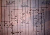
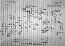
It's time to post the as-built schematic to avoid confusion with all the previous posts.
Test: I trippled up the capacitance after one of the psu chokes to confirm that this reduces hum in the relevant speaker.
But I found a fair bit of ripple on the grid of the output tube - smooth 120Hz. It seems a bad idea to have this kind of ripple on the grid even though it's a low-mu tube. Will have to investigate. Perhaps the choke load on the input tube isn't going to be sufficient to isolate the front end from passing on B+ ripple.
Mechanical hum was explored using a wooden stick between my ear and various parts of the amp. First impression was that the hum was from one of the psu chokes, only one though, not both. Will have to investigate.
Well, I would have done a bit more, but I shorted the cathode of the output tube to ground and blew the 100mA B+ fuse so I'll have to replace that tomorrow
Attachments

Member
Joined 2009
Paid Member
new sport: "Hunt the Hum"
I also swapped out the input tube - the one I have is a rare NOS and I don't want to bu**er it up whilst I mess around. I replaced it with a Westinghouse but that appeared to have a duff half, so ended up with another 6H8C of the less-rare kind. .
RC Filter
======
I whipped out the soldering iron and installed an RC filter made up of a 1k2 and 100uF. Installed it into the B+ supply to the input tube - only one channel of course.
The RC filter had no significant impact on audible hum. So I decided to move the RC filter to the plate side of the choke loading the input tube. This essentially holds the plate at ac ground. Nothing is gonna get through to the output tube grid from there. But still no big impact on hum. Time get out the CRO.
The channel with the RC filter on the plate produced zero ripple at the grid of the output tube - as expected. The channel without the filter had about 100mV p-p ripple at the grid of the output tube.
Looking at the end of the speaker cables (no load) I see 30mV p-p of ripple on the channel with the ac-grounded grid and 38mV p-p of ripple on the other channel. Conclusion: the RC filter on the supply to the input tube is a good idea, removing up to 8mV of hum from the output. But the dominant source of hum at the output remains that from the main B+ supply. So I'll have hunt around for some power resistors to try an RC filter at that point too.
Mechanical Hum
==========
I also removed the psu chokes from the chasis and confirmed they are not a source of mechanical hum. Same for the chokes loading the input tube. The chief suspect remains the power trafo. I installed a wooded heatshield between the tubes and the power trafo. The power trafo still gets quite hot - so this confirms it's not heating up from it's proximity to the tubes but it is self-heating. Conclusion: most likely the trafo is operating at a fairly high loading and this what is producing the mechanical hum.
I'll be back....
Last edited:
Always load a tube amp's output.
I think I mentioned in an earlier post that u'll have a lot of ripple with this small cap. The low impedance triode drops alomost no ripple, the ripple dominates over the higher impedance OPT. You can try some akido, check tubecad,com for that, it works. Or you need to beef up the b+ filtering. I ended up installing a MOSFET based regulator to get it completely quiet.
I use SS rectification, so don't need to worry about stressing the rectifiers with high capacitance.
Other than the hum, have you given the amp a listen? Can the input stage drive the output tube completely?
Member
Joined 2009
Paid Member
Hi SemperFi, yes I have listened to it and like it, like enough that I'm happy to spend the effort finishing it off !
It's not obvious to me how I'd employ the Aikido trick without adding more complexity. I'm going to try the brute force approach first.
So, some more progress today.
RC Filter to B+
============
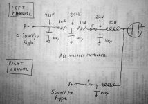
I installed a two pole RC filter into the B+ supply for one channel only so that I could do a direct comparison with what I had before. See attached diagram. The end result was a much reduced level of ripple.
A quick test with my speaker soon told me it was much better than before. I measured around 40mV p-p ripple at the output without the new filtering and this dropped down to around 7mV p-p with the new filtering.
I also added back a separate RC filter to the ht supply feeding the input tube. It reduced ripple on the grid to the output tube as expected. The amp output ripple dropped down further from the 7mV p-p to 5mV p-p.
At this point I wonder if this is good enough. I read that we should be aiming for less than this, as low as 1mV p-p. Now, bearing in mind I will not be using this with speakers more sensitive than 90dB this might not be reqd. Secondly, the rats nest of wires I have right now aren't helping. Even without power to the amplifier I'm picking up at least 1mV p-p of noisy hum due to environmental pick-up.
It's not obvious to me how I'd employ the Aikido trick without adding more complexity. I'm going to try the brute force approach first.
So, some more progress today.
RC Filter to B+
============
I installed a two pole RC filter into the B+ supply for one channel only so that I could do a direct comparison with what I had before. See attached diagram. The end result was a much reduced level of ripple.
A quick test with my speaker soon told me it was much better than before. I measured around 40mV p-p ripple at the output without the new filtering and this dropped down to around 7mV p-p with the new filtering.
I also added back a separate RC filter to the ht supply feeding the input tube. It reduced ripple on the grid to the output tube as expected. The amp output ripple dropped down further from the 7mV p-p to 5mV p-p.
At this point I wonder if this is good enough. I read that we should be aiming for less than this, as low as 1mV p-p. Now, bearing in mind I will not be using this with speakers more sensitive than 90dB this might not be reqd. Secondly, the rats nest of wires I have right now aren't helping. Even without power to the amplifier I'm picking up at least 1mV p-p of noisy hum due to environmental pick-up.
Attachments
Last edited:
Member
Joined 2009
Paid Member
Had a chance to borrow a signal generator ...
I looked at the output of the amp. Given that I'm no longer letting it sit idle but driving a signal into it I followed advice to build a dummy load, in this case 7R7 (3 power resistors in parallel).
Input Gain
========
I measured the gain of the input stage which confirmed that with the choke load, I am realizing the full mu of the tube. The maximum gain of the input tube is x20 at around 1kHz.
Frequency Response
=================
Over the range 10Hz to 30kHz the output looked clean, only the amplitude changed with frequency. Input was kept at 2V p-p.
Between 1.2kHz to 2kHz I was able to hear some very low level 'singing' from what I think was the input tube choke.
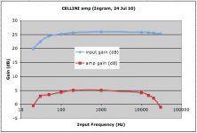
See attached measurement results.
The blue curve shows the gain of the input tube measured at the power tube grid. It falls off at low frequencies (as expected) because of the combination of high plate resistance (>7k) and falling choke impedance.
The red curve shows the gain of the amp measured at the dummy load. It's not a very smooth curve but then my measurements off the scope weren't brilliant either.
With 2V p-p input I'm not driving the output tube as hard as it's capable of, achieving 40V p-p. This is giving me an overall voltage gain at the speaker of X1.8. However, I am expecting my source to provide a larger input signal than this.
I looked at the output of the amp. Given that I'm no longer letting it sit idle but driving a signal into it I followed advice to build a dummy load, in this case 7R7 (3 power resistors in parallel).
Input Gain
========
I measured the gain of the input stage which confirmed that with the choke load, I am realizing the full mu of the tube. The maximum gain of the input tube is x20 at around 1kHz.
Frequency Response
=================
Over the range 10Hz to 30kHz the output looked clean, only the amplitude changed with frequency. Input was kept at 2V p-p.
Between 1.2kHz to 2kHz I was able to hear some very low level 'singing' from what I think was the input tube choke.
See attached measurement results.
The blue curve shows the gain of the input tube measured at the power tube grid. It falls off at low frequencies (as expected) because of the combination of high plate resistance (>7k) and falling choke impedance.
The red curve shows the gain of the amp measured at the dummy load. It's not a very smooth curve but then my measurements off the scope weren't brilliant either.
With 2V p-p input I'm not driving the output tube as hard as it's capable of, achieving 40V p-p. This is giving me an overall voltage gain at the speaker of X1.8. However, I am expecting my source to provide a larger input signal than this.
Attachments
Member
Joined 2009
Paid Member
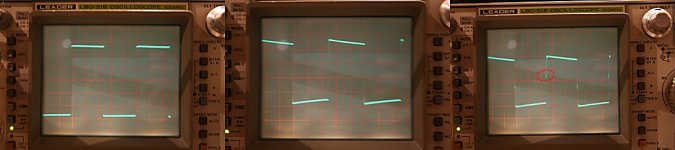
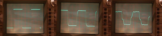
The last thing I did was to look at a square wave test signal. I used 1kHz and 10kHz.
There's something troublesome in the plots I saw. See attached images, the first set of 3 on the left are at 1kHz, the 2nd set of 3 are at 10kHz.
In each case the Left plot is the input, Middle plot is grid of power tube, Right plot is at the dummy load.
At 1kHz the ouput shows a small wiggle as the signal swings from one extreme to the other. I've indicated this with a red circle.
At 10kHz this becomes a lot more obvious.
Something to worry about ?
Attachments
Looks to me like it would be one of the chokes maybe, or OPT? No feedback loop that I can see to cause ringing.
I read an article that said that just as large caps can be bypassed for better performance, chokes can be put in series for the same effect. Or you could try a series resistor.
I wouldn't expect it to be one of the caps bypassing the 1K2's, but you may want to probe there and see.
Also, in post 145, those 10R resistors look a little small. Remember we've shifted from low voltage/high current to high voltage/low current and so you need a larger resistor to have the same effect. I think you could increase R and decrease C.
Also, look at where the fuse is in the power supply. If the fuse blows, there is no discharge path for the 100u cap and it's a safety hazard. (actually I just noticed it can discharge through the other channel, providing they both aren't blown which is unlikely, but still?).
I read some posts back that these tubes seem to have a "sweet spot". Maybe you could build a notch filter for 3KHz and tune out the 3rd harmonic with a 1KHz signal generator? Of course to an extent you would only be canceling out the harmonics of the signal generator, so unless you have a low-THD generator this might be a futile experiment.
- keantoken
Last edited:
Member
Joined 2009
Paid Member
Hi Kean, I agree, I think the most likely culprit is the OT. It's not rated to work well above 15kHz. These air gapped trafo's are strange beasts, a set of practical design compromises needed to achieve good performance and the one's I'm using are the economy version. The wiggles I'm seeing are well above even 20kHz.
The RC filters would benefit from more R, but despite the high voltages I don't want to drop the voltage too much. Of course, the real reason I used them is that I just happen to have a pack of 10R 2W resistors in my junk box leftover from TGM psu. Same story with the caps, I have a bunch of these 100uF 315V caps available.
Well spotted re: safety. All the caps have a small resistor soldered across them so that they are each kept safe. I've shown these bleeders on the diagram in post 141 but I didn't bother for the RC filter experiment - the final implementation will include them. It's a great way to use up those high values that come in the digikey assortment pack
Man, u're learing a lot with this project aren't you?
What OPT are u using?
It almost looks like a crossover artifact u'd see from a class-B PP amp.
Even with the cheapest Edcors I use in my kitchen amp has flat response from about 10-40kHz. The One-Electron jobs give me a flat response from about 7-55kHz.
In my next amp I'm going to use the mid-level Edcors like these:
EDCOR - GXSE15-16-1.7K
Hi Bigun,
You have enough supply capacitance there. Too much is still a problem and may cause the power transformer to run a bit hotter. Possibly make a hum worse as well. This is due to I-R losses from the shorter time needed to charge the capacitance.
I would use a voltage regulator for your first stage. Hey! Sand works well in places that benefit from the characteristics of sand (like no extra heaters). Secondly, use your bleeder to generate a + 30 ~ 40 VDC level, and bias your heaters up. This will greatly reduce hum pickup from your heaters. Works like a charm (I dislike DC heater supplies unless really needed). Two birdies with one rock. Filter that tap with about 10uF. The brand will not affect the sound in any way unless the part is defective.
Try the heater bias first. That may solve most of your issues. I just installed this in a guitar amplifier. Hum is mostly non-existent now, which is very good for a small 12 watt guitar amp.
-Chris
Member
Joined 2009
Paid Member
Hi Anatech,
Thanks for the guidance ! So, I tried connecting the c.t. of the heater secondary to the Cathode of the output tube instead of to gnd. This biasses the heater up to 70V. But there was no measurable reduction in output hum. Admitedly this still doesn't raise the heater until it's more positive than the cathode, but wouldn't you have expected some differences to be observable if the hum was sensitive to the heater bias ?
I tried rotating the OT to the side of the chasis so that it's orthogonal to the power trafo. There was no measurable reduction in output hum.
I added yet another capacitor to the B+ filter which halved the B+ ripple, but resulted in no measurable reduction in output hum. This tells me that better B+ regulation is not the answer.
Then I picked up the choke which is used to load the input tube. I moved it around and twisted it around. Voila - the output hum was extremely sensitive to the position of this choke relative to the position of the psu chokes. Just having them orthogonal was not enough to produce low magnetic coupling.
With only a 1 pole RC filter on the B+ supply (instead of the two I had added yesterday) I was still able to position the input tube choke such that output hum was reduced to around 1 - 2 mV p-p at the dummy load. I conclude from this that I don't need to work any harder to reduce hum - I just have to ensure better positioning of the input tube plate choke when I rebuild this thing to tidy it up. Perhaps the biassed heater C.T. would allow me to get a bit lower still.
I'm all out of spare B+ rail fuses now, with just the two installed in the chasis I'll have to order a few more if I'm going to keep playing around with this
SemperFi,
Yup, I'm having lots of fun here. You know, for the past year I was only doing SS amps and they were all thoroughly worked out in Spice. I was able to check distortion, component power dissipation ratings, temperature dependence, start up thump, PSRR, you name it and I could simulate it. When I built these amps it didn't require much to get a final result, mostly tweaking to account for parasitics and optimization of feedback compensation and output bias. It seemed the professional approach, but it was a bit academic, although I learned a huge amount from this.
The fun is different with this first tube project - I didn't use simulations, just data sheets and some freehand calculations - then I go play with the parts and see what happens. It's fun to learn this way too. I just don't want to learn about getting any HT shocks first hand!
Anyhow, the OT is the famous Hammond 125E series, rated up to 15kHz. I'm going to look for those 'cross over' artifacts again after rewiring the chasis and repositioning a few of the key items along with tidying up the wiring. The good thing is, I really enjoyed the sound from the first working version so any improvements at this stage are just 'gravy'.
Last edited:
Hi Gareth,
Yes, that makes complete sense, given your chassis size. I would highly recommend that you use a resistor in that location rather than a choke. In the event that you are using a choke to maximize plate voltage, try using a constant current source as a plate load instead. Using an LED-BJT CCS, your penalty is about 5 VDC. It also has a flat frequency response, whereas winding leakage in the choke is murdering your very high frequencies. Using a solid state regulator isn't going to pick up magnetic hum like that choke did either. Now consider this, that choke is in the plate circuit. So no gain from the input tube itself. I'm sure that the choke would be more valuable in a preamp project for the phono supply.
The step to a solid state regulator would have done a number of things for you in noise reduction, and also freedom from what the output tube is doing. It would also insulate you from whatever is on the AC line. All large pluses.
One big issue that is waiting to bite you ion the rear though. The maximum heater to cathode voltage rating for most tubes is about 100 VDC. You're getting close to that on the input tube. This is where the heater bias will have most of it's effect, on the input tube. If you have 70 VDC on your output cathode, you're running just over 58 mA of bias. What is the voltage on your plate? I'm still trying to get over a grid bias of -70 on your output. Something seems to be wrong there, but I could be wrong. That 1K2 resistor is dissipating about 4 watts. That is not a trivial amount of heat.
Could you do me a huge favor and email a diagram showing your present configuration, along with approx. voltages and component values (including tube types). I want to get everything straight in my head here. Some of my comments may not apply to this as much as I thought they might.
Finally, don't run your heater bias from the cathode of your output tube. Some audio signal will exist on that point and can be coupled to the cathode of the input tube via the heater to cathode capacitance. Obviously the problem increases as the frequency goes up.
From the top of my head and assuming a 250V supply, your resistor string will begin with a 220K resistor, then a 30K resistor to ground. About 10 uF from the junction of the two resistors to common and use this voltage to bias your heaters. You should see about 30 VDC there. The 30K resistor is fine at 1/2 watt, but the 220K will dissipate about 0.22 watts. Allow for higher ambient temperatures and derate the part to a 2 watt resistor being required. Also, resistors have a voltage breakdown value in addition to the maximum power rating. You'd be surprised at how low this can be for some resistors (50 or 100 volts on the low side). This is another reason to use a 2 watt part, it should have a rating of 300 VDC or better. Otherwise, you must add resistors in series in order to handle the voltage. This circuit eliminated the hum in the little guitar amplifier.
Going back to your output tube. You've lost 70 VDC of swing in the supply already. This will look like a grid voltage of -70 VDC. I can see the tube running into cutoff or clipping. In cases like this, many designs will move to a negative bias supply for the grid and ground the cathode. This increases your maximum power output and eliminates a capacitor from the audio path. It also eliminates 4.1 watts from your heat losses. You do have a B+ fuse for each channel, so you're good for protection against bias loss.
-Chris
Bigun,
Chris's advice is terrific, he's done more amps than I've had hot dinners.....
I actually found that the sound of tubes with an active load - read CCS - was not as pleasing as with a resistor chosen to be around 2.5 times the plate resistance. Again, and as with SS electronics, this is a harmonic artefact thing. One of the most effective ways of tweaking thermionic sonics, I found.
As Chris alludes, it's better to run a slightly higher voltage and use an RC filter than the exact correct voltage with a low drop inductor. The inductor works fine, no question, but it's so EXPENSIVE!! You can use fluro ballasts, one for a 13W fluro, 240V, measures 3.4H and 150R, which is handy, and they are well insulated too! (Not sure about 120Vac ballasts, if you can still get 'em, they are now obsolete of course).
Hugh
I'm considering doing some of my own experiments with tubes. That feedforward regulator works surprisingly well in simulation, despite being so simple, so I may try it out.
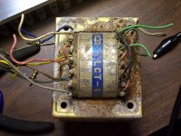
But there's a catch - not sure if this trafo is safe to use! Scavenged it out of an old Akai tape reel anchor that had become the home of many insects. Should it be safe?
EDIT: Yeah, this is sort of OT isn't it...
- keantoken
But there's a catch - not sure if this trafo is safe to use! Scavenged it out of an old Akai tape reel anchor that had become the home of many insects. Should it be safe?
EDIT: Yeah, this is sort of OT isn't it...
- keantoken
Attachments
Last edited:
Member
Joined 2009
Paid Member
OH my gosh Kean, did that come up from a diving expedition !!! Well, I'm not sure I'd be wanting to risk my neck based on those photos. If it were safe it looks to be a handy choice though for some tube experiments. Good to see that you might consider moving to the 'light' side of amplifier design
Member
Joined 2009
Paid Member
I want my first tube amp to be free of SS (allowed only for the protective earth). It's just one of those weird restrictions I placed on this first project for many reasons including the desire to tread the path that many excited hobbyists have trodden before me. So, it has to be a Triode amplifier in the traditional sense, where tubes stand proudly alone 
I'm using a choke load to maximize the gain from the input tube which has a maximum rated mu of 20; I need all the gain I can get because the output tube is a bit of a brute and takes a large swing to wake it up in the morning. The choke does restrict bass extension but I'm measuring an actual -3dB of 30Hz from the input tube which I'm happy with.
Yup, 70V, not for the timid. I'm getting an effective plate voltage of order 175V. I don't have plate curves for the 6H5C tube, but the Svetlana 6AS7 is supposedly very similar and the curves don't look half bad at this operating point. The cathode bias resistor does get hot, it's the main disadvantage of this simple approach. Now, I've not finalized the thermal management of these blighters yet, but it's only a bit of heat, surely that can't be too much to worry over in a amp where the output tube glass can reach 250C
I'll attach it to this post and also ping you an email copy.
I've returned the heater bias C.T. to ground.
Currently, I'm not exposing any resistors to a high voltage, the worse case is the cathode bypass resistor at 70V, but it's a long ceramic girder, looks like it can take some abuse. I was encouraged by the fact even with heater bias at ground I could reduce hum to 1-2mV by repositioning the input tube plate choke.
Yeah, the fixed bias approach seems like a winner and I'm not counting this out at some point if the current approach doesn't yield to a little persistence. I don't want to rely on the fuses to protect me from thermal runaway or have to keep adjusting the bias as things drift so I figure that I'd have to use a mixed bias where I have some cathode resistance and some fixed bias. I have no bias tap on the my power trafo but I can fake one with a resistor and cap. I'd have to introduce another rectifier and since no SS is allowed that means another tube and more load on the heater supply.
Having read such opinions I never made any of my SS amps with a CCS load on the input. But I ought to try it out and hear for myself one of these days. It could be an interesting experiment on the next project.
I think that's where we're at.
Thanks guys !
I would highly recommend that you use a resistor in that location rather than a choke. [...]
I'm using a choke load to maximize the gain from the input tube which has a maximum rated mu of 20; I need all the gain I can get because the output tube is a bit of a brute and takes a large swing to wake it up in the morning. The choke does restrict bass extension but I'm measuring an actual -3dB of 30Hz from the input tube which I'm happy with.
What is the voltage on your plate? I'm still trying to get over a grid bias of -70 on your output. Something seems to be wrong there, but I could be wrong. That 1K2 resistor is dissipating about 4 watts. That is not a trivial amount of heat.
Yup, 70V, not for the timid. I'm getting an effective plate voltage of order 175V. I don't have plate curves for the 6H5C tube, but the Svetlana 6AS7 is supposedly very similar and the curves don't look half bad at this operating point. The cathode bias resistor does get hot, it's the main disadvantage of this simple approach. Now, I've not finalized the thermal management of these blighters yet, but it's only a bit of heat, surely that can't be too much to worry over in a amp where the output tube glass can reach 250C
Could you do me a huge favor and email a diagram showing your present configuration, along with approx. voltages and component values (including tube types).
I'll attach it to this post and also ping you an email copy.
Finally, don't run your heater bias from the cathode of your output tube. Some audio signal will exist on that point and can be coupled to the cathode of the input tube via the heater to cathode capacitance. Obviously the problem increases as the frequency goes up.
I've returned the heater bias C.T. to ground.
[...] Also, resistors have a voltage breakdown value in addition to the maximum power rating. You'd be surprised at how low this can be for some resistors (50 or 100 volts on the low side). [...] This circuit eliminated the hum in the little guitar amplifier.
Currently, I'm not exposing any resistors to a high voltage, the worse case is the cathode bypass resistor at 70V, but it's a long ceramic girder, looks like it can take some abuse. I was encouraged by the fact even with heater bias at ground I could reduce hum to 1-2mV by repositioning the input tube plate choke.
Going back to your output tube. You've lost 70 VDC of swing in the supply already. This will look like a grid voltage of -70 VDC. I can see the tube running into cutoff or clipping. In cases like this, many designs will move to a negative bias supply for the grid and ground the cathode. This increases your maximum power output and eliminates a capacitor from the audio path. It also eliminates 4.1 watts from your heat losses. You do have a B+ fuse for each channel, so you're good for protection against bias loss.-Chris
Yeah, the fixed bias approach seems like a winner and I'm not counting this out at some point if the current approach doesn't yield to a little persistence. I don't want to rely on the fuses to protect me from thermal runaway or have to keep adjusting the bias as things drift so I figure that I'd have to use a mixed bias where I have some cathode resistance and some fixed bias. I have no bias tap on the my power trafo but I can fake one with a resistor and cap. I'd have to introduce another rectifier and since no SS is allowed that means another tube and more load on the heater supply.
Chris's advice is terrific, he's done more amps than I've had hot dinners.....I actually found that the sound of tubes with an active load - read CCS - was not as pleasing as with a resistor chosen to be around 2.5 times the plate resistance. Again, and as with SS electronics, this is a harmonic artefact thing. One of the most effective ways of tweaking thermionic sonics, I found.
Having read such opinions I never made any of my SS amps with a CCS load on the input. But I ought to try it out and hear for myself one of these days. It could be an interesting experiment on the next project.
As Chris alludes, it's better to run a slightly higher voltage and use an RC filter than the exact correct voltage with a low drop inductor.
I think that's where we're at.
Thanks guys !
Attachments
Hi Hugh,
Thank you for your vote of confidence, but that's difficult to live up to.
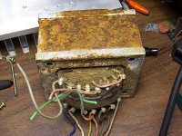
Hi keantoken,
Do you see those four empty bolt holes in the core? Those need to be installed to keep your laminations together. If you ever want to use this transformer, get these bolts installed and tightened down. If you don't do this, and it may be too late anyway, you may be cursed with loose laminations that will buzz like there's no tomorrow!
That transformer may be okay after you clean it up (bolts first!). You may need to bake it in an oven to drive all the moisture out, and that can take hours at a temperature less than 200 °C. Moisture will do all types of very unkind things to your fine wire windings and insulation. You do need to check leakage resistance between the different windings and the core after it's cleaned up. Right now, test for open windings and direct shorts between windings and the core and other windings.
Good luck with this, in a good way.
-Chris
Thank you for your vote of confidence, but that's difficult to live up to.
Hi keantoken,
Do you see those four empty bolt holes in the core? Those need to be installed to keep your laminations together. If you ever want to use this transformer, get these bolts installed and tightened down. If you don't do this, and it may be too late anyway, you may be cursed with loose laminations that will buzz like there's no tomorrow!
That transformer may be okay after you clean it up (bolts first!). You may need to bake it in an oven to drive all the moisture out, and that can take hours at a temperature less than 200 °C. Moisture will do all types of very unkind things to your fine wire windings and insulation. You do need to check leakage resistance between the different windings and the core after it's cleaned up. Right now, test for open windings and direct shorts between windings and the core and other windings.
Good luck with this, in a good way.
-Chris
It almost looks like a crossover artifact u'd see from a class-B PP amp.
To me it looks like ringing on a frequency around 30 KHz.
Last edited:
- Status
- This old topic is closed. If you want to reopen this topic, contact a moderator using the "Report Post" button.
- Home
- Amplifiers
- Tubes / Valves
- my CELLINI triode amp