Member
Joined 2009
Paid Member
And a bit more progress but with some mixed results:
1) I rigged up enough to light up the 6AS7. I tied the grids to gnd via 360k, cathodes were each loaded by 1k2 10W, each resistor in parallel with a Nichicon 100uF cap.
The good news is that the B+ came up gradually and never stressed those psu caps. It topped out nicely at 250V. As far as I can see those psu caps will never get stressed until the power tube blows up and the load disappears. The caps are rated to 315V.
I'm seeing about 6.9V rms on the heater supply, which is at the max level based on Svetlana specifications. Is it good for tube life running it this hot - I suspect not. I have some 0R33 power resistors and I can pop one into the heater circuit a bit later. Nice to see a good orange glow ! .....mind you, you don't want to be brushing yourself against a powered up 6AS7 or you'll be smelling like BBQ'd beef burger")
The cathodes settled out to about 73V and 68V above ground, which translates to a plate current of order 60mA. This looks like pretty good matching between the two triodes to me (i.e. better than 10%) and about what you'd expect from the plate curves. I'm quite pleased about that.
2) Things I'm not so happy about:
In contrast to earlier testing where I used only a resistor to load the power supply there is a now a level of hum, audible within a couple of feet of the speaker plus some mechanical hum from the chasis which seems to be coming from the topside - not sure if the sound appeared to originate from the power trafo or the 6AS7. Can mechanical hum originate from the tube ? I noted that it only starts making a noise when B+ gets up over 100V (when I think it through, the power trafo doesn't hum based on heater current draw alone, nor did it hum with a resistor loading the HT).
And those cathode resistors get really darn hot.
1) I rigged up enough to light up the 6AS7. I tied the grids to gnd via 360k, cathodes were each loaded by 1k2 10W, each resistor in parallel with a Nichicon 100uF cap.
The good news is that the B+ came up gradually and never stressed those psu caps. It topped out nicely at 250V. As far as I can see those psu caps will never get stressed until the power tube blows up and the load disappears. The caps are rated to 315V.
I'm seeing about 6.9V rms on the heater supply, which is at the max level based on Svetlana specifications. Is it good for tube life running it this hot - I suspect not. I have some 0R33 power resistors and I can pop one into the heater circuit a bit later. Nice to see a good orange glow ! .....mind you, you don't want to be brushing yourself against a powered up 6AS7 or you'll be smelling like BBQ'd beef burger
The cathodes settled out to about 73V and 68V above ground, which translates to a plate current of order 60mA. This looks like pretty good matching between the two triodes to me (i.e. better than 10%) and about what you'd expect from the plate curves. I'm quite pleased about that.
2) Things I'm not so happy about:
In contrast to earlier testing where I used only a resistor to load the power supply there is a now a level of hum, audible within a couple of feet of the speaker plus some mechanical hum from the chasis which seems to be coming from the topside - not sure if the sound appeared to originate from the power trafo or the 6AS7. Can mechanical hum originate from the tube ? I noted that it only starts making a noise when B+ gets up over 100V (when I think it through, the power trafo doesn't hum based on heater current draw alone, nor did it hum with a resistor loading the HT).
And those cathode resistors get really darn hot.
Hi,
They are from the chokes.soon you will found they are too small for the job. See the size of your chokes they are smaller then the output tranny.you have 60ma run thru output but 120ma thru the chokes.You need a choke at lease twice the size of output to handle.I'm no expert some one will tell.
Have fun.
Cheers!
SS
Member
Joined 2009
Paid Member
it's tough to localize the sound at this frequency.
Maybe it helps to put a piece of metal/aluminum rod to the respective component and use as some kind of "hearing aid"...
Member
Joined 2009
Paid Member
Maybe it helps to put a piece of metal/aluminum rod to the respective component and use as some kind of "hearing aid"...
I had thought about that, but the idea of a conductor between my head and the inside of the chasis didn't appeal

I put a scope on it this morning. The B+ looks clean, with 500mV of pk-pk ripple. Is that good ?
The output terminals (no speaker load) have 30mV pk-pk of ripple plus a little spike on the shoulder of the waveform. Now, for good or bad I have a wire connected to each grid of the output tube ready for connection to the input tube and these wires could be acting as little pick-up antenna allowing some crap to reach the grid even though the grids are grounded via 360k. I need to check it again tonight with these wires shunted to ground instead of flapping around in the breeze.
I wonder if the power supply chokes might benefit from being isolated from the chasis with some rubber washers too.
I had thought about that, but the idea of a conductor between my head and the inside of the chasis didn't appeal
I wonder if the power supply chokes might benefit from being isolated from the chasis with some rubber washers too.
That's what I meant... of course not to stick the metal rod into HV and accidentally change your hairstyle, but check the chokes/transformers for vibration causing the slight hum....
Sure it is worthwhile to put the chokes on rubber washers.
Member
Joined 2009
Paid Member
The good thing is, this project has the real flavour of DIY. I don't mean the kind of project where we try to make it professional... dare I say almost commercial looking and fit for a marketing brochure. No, this one embodies the spirit of the crazy inventor from a bygone era. The smell of old, full of character - a half cut chasis, a couple of scratches here and there, bits of wood, some glue, wires all over the place, dangerous voltages, bits that glow in the dark, a couple of switches and most important it hums. A classic. It doesn't get any better than this
Member
Joined 2009
Paid Member
compliant material installed between all trafo's and the chasis, 0R33 in series with output tube heater supply (drops it nicely to 6.2V).
mechanical hum unchanged, although it's no worse than the hum from my oscilloscope. Perhaps this is a normal level, I've got nothing to benchmark it against ??
ensuring a better ground for the power tube grids cleaned up the glitches in the output ripple, which is still audible with the same amplitude as before.
Member
Joined 2009
Paid Member
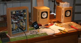
It works !
Instead of fixing the hum I decided to go for gold and do some temporary wiring up of the input tube and install it.
Added 0r33 in series with the rectifier heater circuit since it's not fully loading the trafo the voltage is probably a bit high.
End result - powered up and voila, 3 glowing bottles.
Music in stereo
Attachments
Gareth,
Despite the criticism here, the 6AS7 can work extremely well as an SRPP output stage, cap driven to the trafo (4.7uF, filmcap, 160V). I have built such a beast and it sounds much better than the standard topology you have used here. Then you can use a 15W 100V line output transformer, at greatly reduced cost, and with the SRPP configuration, Zout is much lower and so more drive and sensitivity. In this instance, the 6SN7 is fine.
The lower section of the 6AS7 should be bypassed at the cathode, of course.
Hugh
Hi,
You can change the filter to R C L C then you'll have a very smooth B+.changing the R value you can get whatever you want up to 400V.PsduII will tell.
My suggestion look at the 6as7g data sheet for audio use (attached) View attachment 6AS7G[1].pdf
use B+200V bias 90V 1.5k Rk total 300V a few volt drop for dcr of the output.
Your chokes will work happy with no noise.But with two more hot resistors.
Have fun
Cheers!
SS
Member
Joined 2009
Paid Member
Hugh, this must bring back some memories for you !
I've also noticed that the 6AS7 is popular in push pull (SRPP etc) for canceling out H2. It's a good looking tube, although the one I'm using is actually a Russian equivalent, mil quality control.
Singh Santa, I'm reluctant to use a capacitor loaded supply for all the reasons people talk about when comparing them to choke loaded supplies. Still, I will have to do something to reduce B+ ripple and I'll give this some thought. From the data sheet for this tube I'm already at a good bias point. My cathode sits at 70V and B+ at 250V so I'm getting a plate voltage of 180V which looks to be good for this tube. I'm wondering if I can use any of the Broskie Aikido ripple canceling tricks without introducing another tube.
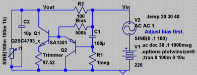
I'll post my adventure in the simulator. I'm not familiar with HV design much but here is a quick attempt at a simple design. Don't know how solid state compares to burning state here... Depending on input ripple quiescent of Q1 can be reduced. - keantoken
Attachments
Member
Joined 2009
Paid Member
Hi Kean,
Excellent idea ! - for high voltage and low current typical of tube psu's a shunt regulator looks very well suited. I think Broskie is a fan too.
I'd better verify that the B+ ripple is the main culprit before considering this approach. I'm thinking of adding additional filter capacitance to the B+ of one channel and then comparing the two channels to see if this has a clear impact.
Progress on the amp came to a halt tonight.
I got as far as hooking it up to my big speakers (PMC's) in the basement, adding my YBA cd player as the input and noting that the volume (I have no volume control) was just right for listening by some strange reason of coincidence.
It's the first time I've allowed the amp to reach operating temperature and I reckon the sound changed. It took about half an hour to stabilise - although that could have been my ears adjusting to the change of speaker.
The power transformer was uncomfortable to put a hand against for more than a few seconds - meaning it is up at around 55degC. I don't see this as a problem, but I'm suspicious that it is the loading on the power trafo that produces the mechanical hum. The psu chokes get slightly warm but nothing to worry about.
On my big speakers I get the bass that my little speakers can't handle. I noticed immediately that the bass goes very low, but it is also a little bit 'wooly' compared with any of my SS amps. Given the difference in damping factor I don't see this as a fault.
Next, I noticed the quality of the percussion instruments - they were very 'real'. Cymbals didn't have a 'sssss' sound, but rather they sounded like, well, cymbals. It surprised me because I hadn't realized until now that my SS amps were not performing as well as they could in this regard. Every voice and instrument appeared to be properly 'separated' - if that's the right word, each one clearer, more real, well I'm not sure what the right way to describe it, but I think I've discovered with my own ears why people like this kind of amplifier - I couldn't stop listening to the music.
Last edited:
The difference between a shunt and feedforward regulator is that the feedforward only subtracts ripple from the output, it doesn't regulate the voltage. Voltage depends on loading, so you will need adequate filtering caps. Seems to me that such a regulator would sonically transparent, since it doesn't deal with the signal at all.
Here is a page showing a feedforward and shunt made from tubes.
Aikido PCB & Broskie OTL & Feesforward Shunt Regulator updates
- keantoken
Here is a page showing a feedforward and shunt made from tubes.
Aikido PCB & Broskie OTL & Feesforward Shunt Regulator updates
- keantoken
Gareth,
Despite the criticism here, the 6AS7 can work extremely well as an SRPP output stage,
Hi Hugh,
Do you have a schematic?
I wanted to build this but the B+ was too high for my power transformer.
http://www.diyaudio.com/forums/tubes-valves/7692-emperors-new-clothes-sound-tubes-8.html#post84773
Hi Gareth,
Excellent! You got sound and a working project, which is far more than some people achieve. Enjoy it for a while before doing anything more ... except for one thing. Open up some ventilation holes to lower the temperature of the under chassis components. Those output transformers will be getting warm after a while, and that's normal when mounted in the light. Some holes around the power tube sockets will help as well.
Later on, I would reduce the value of your interstage coupling capacitor. It's normal to size it in such a way that you cut the bass off before the low frequency cutoff of your output transformer. That will really clean up the sound at higher volume levels. This is error # 1 that people make when "improving" amplifiers. The coupling caps get sized far too large. In my opinion, the same is true for the power supply capacitors.
If you get stuck on the hum, you're always welcome by here and we can both have a peak at it. I'd like to see these in the flesh at some point in time.
-Chris
Member
Joined 2009
Paid Member
Thanks Anatech. I hear what you say about not feeding the OT with too low frequency. The original idea was to undersize the output tube cathode bypass capacitor to cut things off but the Sprague Atoms I have are only 65degC and only 20uF and there isn't space under the hood for them. I'm saving these rather nice caps for the next project. So I used a single Nichicon 100uF cathode bypass. I figure that this is probably better since distortion in electrolytics is lower when you use big caps so I actually question the practice of some people who use smaller cathode bypass caps.
And as a result I have done as suggested. The 1um PIO caps are replaced with some MKP 630V film caps of 0.22uF.
Having said this, my input stage provides some l.f. cut off anyway because the 6SN7 has a fairly high plate resistance and the choke load has a low resistance at low frequencies.
I should get a signal generator and test it shouldn't I !
Will be looking carefully at the thermal management - I'm tempted to move the cathode bypass resistors up top still.
Thanks for the kind offer in sorting out the hum, I may have to take you up on it !
Hi Gareth,
Well, we have everything we would need to measure cutoff right here. We can also do a sweep if you would like. You are always welcome over here, an open invitation.
The coupling caps are where you want roll off low frequencies. Never in the cathode circuit. Your under chassis temperature problems will also come from outputs and any chokes mounted down there. They all throw off heat. With a power transformer mounted over top, everything will cook. They are thermally coupled by the chassis and both are pouring heat into a very limited heat sink (your chassis). You need airflow, maybe even forced air depending on how cramped your chassis is. Personally, I thought the original layout looked fine on the full sized chassis. The idea to split up the main power supply and the amps was a good one. The chassis' would match, wouldn't they? This is still an option, plus they would be easier to carry.
-Chris
- Status
- This old topic is closed. If you want to reopen this topic, contact a moderator using the "Report Post" button.
- Home
- Amplifiers
- Tubes / Valves
- my CELLINI triode amp