RX5,
I have been following the forum that you started. You were really into it. You made it.
Do you mind if I can build the same thing you did? I mean can you posibly give me a link or better yet a construction guide (schematics, parts used) of your project? A lot of links are involved and I cant spend too much on the internet because I am just renting a unit from an internet cafe.
email: roddeasis@yahoo.com
Thanks ka'bayan!
hello roddeasis,
since you have been -following- THIS thread, I suppose you already know I have posted already 3? schematic diagrams...")
pls read and understand all my earlier posts... you will learn from it...
almost all the info IS there...
took me MANY months to perfect it(on what im currently using now)....
experiment/simulate....
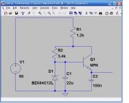
try this one out on SIM
http://www.nxp.com/acrobat_download/usermanuals/UM10155_1.pdf
cheers,
Raff
since you have been -following- THIS thread, I suppose you already know I have posted already 3? schematic diagrams...
pls read and understand all my earlier posts... you will learn from it...
almost all the info IS there...
took me MANY months to perfect it(on what im currently using now)....
experiment/simulate....
try this one out on SIM
http://www.nxp.com/acrobat_download/usermanuals/UM10155_1.pdf
cheers,
Raff
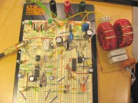
stereo diy
finally a stereo ... still looking for identical gapped ferrite cores for coils as output filter/s...
after puting it inside a casing, I will experiment on bridging them...
finally a stereo ... still looking for identical gapped ferrite cores for coils as output filter/s...
after puting it inside a casing, I will experiment on bridging them...
An externally hosted image should be here but it was not working when we last tested it.

Hello kartino,
thanks!
i just love challenges.... my most ambitious project ever.. but with GOOD results... you tend to learn more while your into it...
PS. still not a master of 'UCD' ... Bruno is ..... i still have a lot to learn...but im not very far from there... i can see the light already.. hehe
thanks!
i just love challenges.... my most ambitious project ever.. but with GOOD results... you tend to learn more while your into it...
PS. still not a master of 'UCD' ...
Bruno is ..... i still have a lot to learn...but im not very far from there... i can see the light already.. heheHi RX5
That's really a nice job Congratulations
What is the switching freq? (you probably already told us somewhere in the post).
Are you using LM7812 for high side supply?
Looking forward to hering the first feedback on the sound from the stereo pair
I'm trying out an LM317 for this job, and it seems that it heats up quite a lot more than the LM7812 types that I have used in a similar circuit
I have also used LM317/LM337 for the oscilator circuit and these heats up even more??
The osc i based on a LM319 using 2k2 collector resistors driving +-12V at 250 kHz.
The input voltage is only +-30V ..... any one have some similar observations? Maybe these regulators are more "unstable" or something .... but I guess thaese are used in many other switching applications ....
Have tryed decoupling with small caps, large caps, and placed colose to the regulator and further from etc. ... no change.
I'm considering making the regulations with descrete components instead .... might do a better job ..... or even making a pre-regulator .... but then it seems a bit too complex and a bit too much!
That's really a nice job
Congratulations What is the switching freq? (you probably already told us somewhere in the post).
Are you using LM7812 for high side supply?
Looking forward to hering the first feedback on the sound from the stereo pair
I'm trying out an LM317 for this job, and it seems that it heats up quite a lot more than the LM7812 types that I have used in a similar circuit
I have also used LM317/LM337 for the oscilator circuit and these heats up even more??
The osc i based on a LM319 using 2k2 collector resistors driving +-12V at 250 kHz.
The input voltage is only +-30V ..... any one have some similar observations? Maybe these regulators are more "unstable" or something .... but I guess thaese are used in many other switching applications ....
Have tryed decoupling with small caps, large caps, and placed colose to the regulator and further from etc. ... no change.
I'm considering making the regulations with descrete components instead .... might do a better job ..... or even making a pre-regulator .... but then it seems a bit too complex and a bit too much!
Baldin said:Have tryed decoupling with small caps, large caps, and placed colose to the regulator and further from etc. ... no change.
I'm considering making the regulations with descrete components instead .... might do a better job ..... or even making a pre-regulator .... but then it seems a bit too complex and a bit too much!
Hello Baldin,
nice to hear your doing the UCD diy way...
using 7812 and other 3 pin IC regulators ... never tried... max input is only 35V(i think) check datasheet...
anyways, UCD uses discrete regulator to power the op-amp buffers/start-up delay....
ghemink has posted the circuit somewhere in this forum... its a series pass transistor regulator.. using darlington type/s....
..
ok here it is....
im using TIP102/TIP107 for the regulators... kinda overkill 100V/8A
Attachments
Hi RX5
Yes the LM78xx are quite limited with regards to input voltage, but the LM3x7 cna handle e difference of 40V between Vin and Vout.
I thought the integrated regulators would work better especially for the input stage due to the much higher ripple rejection compared to a simple discrete circuit.
But now I'm not so sure
Think I'll try a discrete regulator. Think it's a good idea to use a darlington as it will provide a much better ripple rejection without using more components.
It's actually not for a UCD. It's using a bit different topology, but I will try to take some feedback after the filter.
hi,
the regulator will have quite high difference for Vin and Vout. Hence you must consider, let say for 1A from 35V to 12 V will dissipate (35-12)W. That's why the regulator is getting hot. Using chip or discrete are same since chip also do the same way to drop the voltage.
the regulator will have quite high difference for Vin and Vout. Hence you must consider, let say for 1A from 35V to 12 V will dissipate (35-12)W. That's why the regulator is getting hot. Using chip or discrete are same since chip also do the same way to drop the voltage.
RX5:
Sure it is working
Though on a breadboard it has it's limits e.g. it starts distort at relatively low output.
Well the IRF540 handles higher currents and has lover Rds(on), but is not as "fast" as the IRF640 .... a bit of a compromise
I think I'll try to get hold of some STW34NB20, these might be some of the best for the job I think.
Kartino: After a bit more thinking, you calculation is also only valid for DC I think. Here we're talking about relatively high frequencies at moderate currents.
To get the higher ripple rejection the chips uses higher feedback, and it might not be entirely stable . Or it might a bit too well at higher frequencies, not limiting the current well enough. Driving square waves could produce very high peek currents in the regulator, if the bandwith is too high and the current limit is not adequate. This could very well heat it up quite good.
A discrete circuit will not deliver as high ripple rejection and might not work that well at very high frequencies, but it might do the job better not heating nearly as much.
Baldin said:Kartino: After a bit more thinking, you calculation is also only valid for DC I think. Here we're talking about relatively high frequencies at moderate currents.
To get the higher ripple rejection the chips uses higher feedback, and it might not be entirely stable . Or it might a bit too well at higher frequencies, not limiting the current well enough. Driving square waves could produce very high peek currents in the regulator, if the bandwith is too high and the current limit is not adequate. This could very well heat it up quite good.
A discrete circuit will not deliver as high ripple rejection and might not work that well at very high frequencies, but it might do the job better not heating nearly as much. [/B]
Hi,
Are we talking about regulator for gate driver for the diy ucd? If yes IMHO the regulator is nothing to do with switching frequency since the output connected to quite big caps, for higher and low gate. you can simulate that the load of regulator is almost flat at DC.
What kind of chip did mentioned, linear or switching. If you find simple switching chip, it will be better. There are some step down purpose ic for high dropping regulator.
RX5!
There are several parameters determining "speed", and some of them are contradictional. Rise time and fall time affect efficiency, delay times are important in feedback phase shift, reverse recovery time and charge affect efficiency, EMI radiation, and distortion.
If you want to compare two device, then you have to take account every of above mentioned.
One more thing: there are different subtype of IRFXXX. Eg.: IRF640 manufactured by IR, Harris, Fairchild, ST, and even IR have more different devices: IRF640N, L, S, etc... IRF540 has one more significantly different variant: IRF540Z. These variants are optimized for different features.
Pafi said:RX5!
There are several parameters determining "speed", and some of them are contradictional. Rise time and fall time affect efficiency, delay times are important in feedback phase shift, reverse recovery time and charge affect efficiency, EMI radiation, and distortion.
If you want to compare two device, then you have to take account every of above mentioned.
One more thing: there are different subtype of IRFXXX. Eg.: IRF640 manufactured by IR, Harris, Fairchild, ST, and even IR have more different devices: IRF640N, L, S, etc... IRF540 has one more significantly different variant: IRF540Z. These variants are optimized for different features.
ok Pafi.. got it! thanks....
all the IRFxxx here in my area are IR made.... so I download IR datasheets...
AND i havent noticed there WAS as difference with the IRF540 and IRF540N....
I am using IRF540N
It should also be mantioned that the switching times for different devices are measured and stated at different conditions like Vd and Id.
I totally agree that it's not that easy to determine which device is actually the best
I'm using the "normal" IRF640 as these where the cheapest
Could anyone point to a proper upgrade?
They'll go into a 400 W H-Bridge construction for a sub.
I totally agree that it's not that easy to determine which device is actually the best
I'm using the "normal" IRF640 as these where the cheapest
Could anyone point to a proper upgrade?
They'll go into a 400 W H-Bridge construction for a sub.
Hello all,
been doing datasheet comparisons between IRF mosfets... would like to replace my existing IRF540N since it was a slower switcher....
IRF640 = 200V 18A
IRF740 = 400V 10A
IRF840 = 500V 8A
I guess the 740 would do it?? has "better" specs that 640... 840 has only capacity of 8 amps(so it wont do) ..... might as well try IRF740N...
or am I missing something else..
EDIT: oooppps i spoke too soon... I guess IRF640N would be it.... seems there is NO IRF740N or IRF840N... hehehe
- Status
- This old topic is closed. If you want to reopen this topic, contact a moderator using the "Report Post" button.
- Home
- Amplifiers
- Class D
- my 1st ever D-amp, WORKING!!!