regs
Yes scrape the pcb and use as a ground, Some use caps on input and output for smoothing, ive built a small pcb using a 7805 2 caps and an led to show its working ok.
alan
"use the top screen". Do you mean scrape the PCB and solder there?
Do I need some additional components on the input or output of the reg?
Yes scrape the pcb and use as a ground, Some use caps on input and output for smoothing, ive built a small pcb using a 7805 2 caps and an led to show its working ok.
alan
Yes scrape the pcb and use as a ground, Some use caps on input and output for smoothing, ive built a small pcb using a 7805 2 caps and an led to show its working ok.
alan
OK, I understand.
Thanks for the info.
I have a problem with my CD67 which I hope is easy to fix, the drawer opens fine but closes very slowly and it refuses to read discs and I get no laser light. This is after replacing my op-amp based regs with 7805's. I can't see any issues with the 5V supplies and the three servo chips are getting 5V each.
I have a problem with my CD67 which I hope is easy to fix, the drawer opens fine but closes very slowly and it refuses to read discs and I get no laser light. This is after replacing my op-amp based regs with 7805's. I can't see any issues with the 5V supplies and the three servo chips are getting 5V each.
Opamp supply should be +/- 12V , 7812 and 7912 are default regulators, are you sure you replaced them with 7805? I heard people going higher, but not lower

Regards
Marko
Opamp supply should be +/- 12V , 7812 and 7912 are default regulators, are you sure you replaced them with 7805? I heard people going higher, but not lower
Regards
Marko
Scratch that, I misunderstood your problem, sorry.
Can you revert to the regulators you were previously using to check?
Regards
Marko
re regs
Each of the servo chips should have +- 11v or there abouts thats your problem
where have you put the regs.
I have a problem with my CD67 which I hope is easy to fix, the drawer opens fine but closes very slowly and it refuses to read discs and I get no laser light. This is after replacing my op-amp based regs with 7805's. I can't see any issues with the 5V supplies and the three servo chips are getting 5V each.
Each of the servo chips should have +- 11v or there abouts thats your problem
where have you put the regs.
servo
Sorry ray had a blonde moment thought it was a cd63 67 servo regulated.
alan
No, the CD67 servo's have a regulated single 5V supply, so looks like it's o.k.
Ray
Sorry ray had a blonde moment thought it was a cd63
67 servo regulated.alan
Hi
I have a problem with my CD67. I recently changed laser unit. After changing new one it is not reading any disc. I tried it in service mod. It plays when switch over to mod 3. If I press play button it is showing ERROR 10. Any suggestions?
Thanks
Badri
Hi Badri,
Must be something wrong with the new laser then, or maybe you didn't change it correctly. Have you replaced the complete assembly, including the disc and sled motor, or just the optical unit?
Ray
Decoder mistake
Hi all
According to an old post from Brent,
http://www.diyaudio.com/forums/digital-source/54009-marantz-cd63-cd67-mods-list-339.html#post959994, Marantz made a small mistake with the decoder circuit.
I was wondering if it's important to fix this when adding separate regs to the decoder, or should I just leave it as it is?
Don't know if it will make a lot of difference soundwise, but if you're working on the decoder area anyway, you could change it. Marantz' schematic is not conform the decoder datasheet.
Marantz fixed this in the CD63 MkII KI player and did some changes to the decoder circuit. So this is not a problem in my player.
Oh, so it's an mkI problem. Didn't know that
May be I was wrong, from my experience even MKII KI has the same wrong connections in the PCB. I need to make some changes in the PCB to ensure the +5V supply to the digital and analogue circuits of the Decoder are correct.
See page 1911 thread #19107 and compare the PCB copper connections:
http://www.diyaudio.com/forums/digital-source/54009-marantz-cd63-cd67-mods-list-1911.html
Last edited:
May be I was wrong, from my experience even MKII KI has the same wrong connections in the PCB. I need to make some changes in the PCB to ensure the +5V supply to the digital and analogue circuits of the Decoder are correct.
See page 1911 thread #19107 and compare the PCB copper connections:
http://www.diyaudio.com/forums/digital-source/54009-marantz-cd63-cd67-mods-list-1911.html
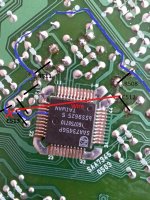
You are correct highlander, the PCB layout around decoder is a bit different but the mistake is still there. I took the board out to trace.
The blue line in the pic shows that 5v go straight to pin 15 without going thru R508.
The fix is to cut the track between R511 and C513, near C513.
Then wire from C512 (pin 44) to C513 (pin 15).
I think I am correct on this.
Attachments
You are correct highlander, the PCB layout around decoder is a bit different but the mistake is still there. I took the board out to trace.
The blue line in the pic shows that 5v go straight to pin 15 without going thru R508.
The fix is to cut the track between R511 and C513, near C513.
Then wire from C512 (pin 44) to C513 (pin 15).
I think I am correct on this.
Fixed this on the decoder circuit. Also added separate regs (only 7805, SPowers later).
3x DAC
2x Decoder
2x Servo
Sound is now much cleaner and powerful, better bass. Less digital.
- Home
- Source & Line
- Digital Source
- Marantz CD63 & CD67 mods list