Hi Lymmlad,
Yes, I've currently got 4 separate secondaries powering my DAC and two (one each) for servo and servo control. Almost every power pin has its own reg and 470uF Black Gate (FK/NX for analogue/digital respectively). The only exceptions are the DAC analogue pins, which are paired together and can't easily be given the same treatment. Oh yeah, and I have 22,000uF Mundorf smoothers pre-reg on each of those. I'll be adding more soon to further isolate the decoder and servo control supplies.
Ben, thanks for this. I've decided my next move will be to power the DAC separately with 1 tx for the digital section and 1 tx for the analogue. Just need to work out where to put the trannies!
Incidentally, out of the mods I have done so far, the one that made the biggest SQ improvement was the separate power supply, with separate tx and big smoothing caps, for the servo. I had previously re-clocked servo and DAC with separate tx and big smoothing caps. I've since done sep tx (with big caps) feeding the output stage + new opamps and HDAM bypass; but this did not have as big an impact as the servo p/s mods.
Out of interest, what mod made your biggest improvement?
"many small steps make one giant leap"
Plan ahead what you wish to do and you will find taking out the mother board out of the case is not that annoying after all. That was my own experience
To be frank I did not have experiencing having to do the same job twice and every mod was successful with only one take. May be I am the lucky one
Totally agreed that changing the stock TX with bigger TXs for the servo and the analogue section together with bigger smoothing caps have the biggest impact on SQ.Ben, thanks for this. I've decided my next move will be to power the DAC separately with 1 tx for the digital section and 1 tx for the analogue. Just need to work out where to put the trannies!
Incidentally, out of the mods I have done so far, the one that made the biggest SQ improvement was the separate power supply, with separate tx and big smoothing caps, for the servo. I had previously re-clocked servo and DAC with separate tx and big smoothing caps. I've since done sep tx (with big caps) feeding the output stage + new opamps and HDAM bypass; but this did not have as big an impact as the servo p/s mods.
Out of interest, what mod made your biggest improvement?
Next will be the fitting of good quality low jitter clocks to the DAC and the servo.
After that using good quality low and high filtering caps and low noise regulators will further enhance the SQ.
Last of all try using discrete opamps or DOS.
That was my experience after modding eight CD63s
Totally agreed that changing the stock TX with bigger TXs for the servo and the analogue section together with bigger smoothing caps have the biggest impact on SQ.
Next will be the fitting of good quality low jitter clocks to the DAC and the servo.
After that using good quality low and high filtering caps and low noise regulators will further enhance the SQ.
Last of all try using discrete opamps or DOS.
That was my experience after modding eight CD63s
That's 8 and still counting, no doubt! I'm a newby and still on my first! Thanks for your view on what makes a difference to SQ.
After the DAC mods (digital and analogue) that I plan to do next, I might have a go at the DOS. I already have one of Ray's DOS boards... just need to make some room for it... and get the parts of course.
Plan ahead what you wish to do and you will find taking out the mother board out of the case is not that annoying after all. That was my own experience
To be frank I did not have experiencing having to do the same job twice and every mod was successful with only one take. May be I am the lucky one
I have taken the board out around 20 times. Its become a weekly routine by now
I have done a lot to the player. Modified nearly every section and the sound is awesome.
Yet, I haven't touched the drivers IC section. And I still have to add low jitter clocks and separate regulators, which will have huge improvement to the sound.
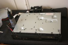
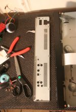
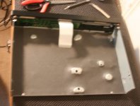
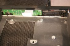
Do you mean something other than the standard access panel? I haven't done it on mine, but I understand there's a specific section stamped out of the base that's designed to be easily removed with snips and (I believe) flips round 180 degrees and can then be screwed back on.
Not sure which parts of the board specifically it gives access to, but it's only a section of it.
I might give that a go on mine actually. I'm fed up with removing extra power supplies and such to do a simple job on the underneath.
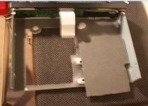
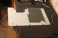
The base of mine does not have a section which can be 'snipped out' (mine's a KI Signature), but I've worked out that a section can be cut out to give access to most of the underside of the pcb. It's a pain to have to remove everything (flea boards, etc) to get at the underside. It also puts a strain on the wires that are soldered directly down to the board. You are lucky if yours can be removed easily.
I have spoken with a guy at a crash repair shop, and he has asked me to take it in so he can have a look at it. He'll be able to give me an idea of whether he can do it or not.
So, when the square is removed, it can be screwed back onto the steel underplate (and/or spot welded to the plate), and the steel plate screwed back in position. So, to access the underside of the pcb, all I need do is unscrew the bottom steel plate – 4 screws. And presto! The steel plate will come away along with the square that has been cut out.
Hi Lymmlad, I've only done this once so I only have one experience to draw from, unlike others here. The big ones for me in retrospect were probably servo PSU with larger caps, Fleas, DOS and separate regs. There have been lots of little UPS and downs along the way though.
I have a spare base and lid, but need the front panel and copper screws, maybe want to keep the feet too.
Timjar: thanks for responding. I need the base, lid, front panel and back panel. Not bothered about the copper screws nor the feet. What model is it?
Hi Lymmlad, I've only done this once so I only have one experience to draw from, unlike others here. The big ones for me in retrospect were probably servo PSU with larger caps, Fleas, DOS and separate regs. There have been lots of little UPS and downs along the way though.
Thanks, Ben. Thumbs up to the 'ups and downs along the way'.
Hi Guys,
I need help on my 67MK2. After Ray's Mod instructions it was rebuilt and now I notice the following error.
It runs without problems and after about 15minutes it starts to rush and is always more to any music to listen more.
After 3-4 minutes I switch back on and the noise is gone for.
Apparently a hot component.
Does anyone have an idea what the problem starts?
I suggest to start with an easy one first. Clean all the plugs with contact cleaners and ensure there are no bad contacts.Hi Guys,
I need help on my 67MK2. After Ray's Mod instructions it was rebuilt and now I notice the following error.
It runs without problems and after about 15minutes it starts to rush and is always more to any music to listen more.
After 3-4 minutes I switch back on and the noise is gone for.
Apparently a hot component.
Does anyone have an idea what the problem starts?
I have set up a toroidal tx (with 2 secondaries each hooked up to a daughter board carrying diodes, smoothing cap, +5V regulator + cap) to power the 2 DAC analogue rails. I have looked at the circuit board but cannot work out where to hook up the connections.
Also I have set up another toroidal tx (with 1 secondary hooked up to a daughter board carrying diodes, smoothing cap, +5V regulator + cap) to power the 1 DAC digital rail. Again, I have looked at the circuit board but cannot work out where to hook up the connections.
If someone could assist here I would be much obliged.
I do not think it is up to the terminals. He plays at the beginning of normal
and begins to roar with the times! I suspect a problem with the opamps,
But can not find any fault. First I had a problem with the heat
Voltage regulator on the "flow" Clock Platine.Das I had actually solved.
and begins to roar with the times! I suspect a problem with the opamps,
But can not find any fault. First I had a problem with the heat
Voltage regulator on the "flow" Clock Platine.Das I had actually solved.
Please refer to the circuit diagram attached.I have set up a toroidal tx (with 2 secondaries each hooked up to a daughter board carrying diodes, smoothing cap, +5V regulator + cap) to power the 2 DAC analogue rails. I have looked at the circuit board but cannot work out where to hook up the connections.
Also I have set up another toroidal tx (with 1 secondary hooked up to a daughter board carrying diodes, smoothing cap, +5V regulator + cap) to power the 1 DAC digital rail. Again, I have looked at the circuit board but cannot work out where to hook up the connections.
If someone could assist here I would be much obliged.
Remove everything on the PCB before +/- 12V; +/-5V and the +/-10V.
Then connect your two TXs' outputs to the +/-12V; +/-5V and the +/-10V positions. Ensure the connections and porities are correct to avoid short circuits and causing damages.
Don't forget the AC power source supplying power to the muting control circuits (the connections after the two fuses !!)
You need to trace the copper straps and compare them with the circuit diagram to identify the exact connection points. Sorry no fast and easy way out
Attachments
Last edited:
- Home
- Source & Line
- Digital Source
- Marantz CD63 & CD67 mods list
