Okay,
Got bold and hooked up PB-1079 output and feedback correctly and amp comes out of protect with 100mV of DC.
Will solder these connections and adjust DC offset.
It must have been the disconnection of the resistor lead mounted on the back of the PB-1079 board.
Need to get back to the left channel oscillation issue.
Thanks sgrossklass for working with me on the right channel. Please stay on board for the left channel oscillation investigation.
Good to hear you got that sorted. Which resistor did that disconnected lead belong to? Something in the feedback, I guess...
Now as to the original problem, I'm afraid I'm slightly stumped there. Something has got to be different between the channels. Check the corresponding Zobel network on PB-1081 (R512a/b = 4R7 5W, C505a/b = 0.22µ >63 V) and whether it has a good solid ground connection.
Now as to the original problem, I'm afraid I'm slightly stumped there. Something has got to be different between the channels. Check the corresponding Zobel network on PB-1081 (R512a/b = 4R7 5W, C505a/b = 0.22µ >63 V) and whether it has a good solid ground connection.
Sgrossklass, good to hear from you.
Yes i was relieved to get right channel straightened. Can get disheartening when things start going backwards.
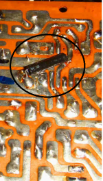
The resistor was a factory oops. They soldered it on the backside. No thru holes available. It connects two of the DML pins and without it correct base voltage for the first and second input transistors can not be achieved.
Bypassed miller caps on PB-1079 with bypass caps. No change.
Will look at what you just mentioned zobel circuit.
Time spent figuring out how to get to the output board will pay off now.
Yes i was relieved to get right channel straightened. Can get disheartening when things start going backwards.
The resistor was a factory oops. They soldered it on the backside. No thru holes available. It connects two of the DML pins and without it correct base voltage for the first and second input transistors can not be achieved.
Bypassed miller caps on PB-1079 with bypass caps. No change.
Will look at what you just mentioned zobel circuit.
Time spent figuring out how to get to the output board will pay off now.
Last edited:
the oscillation doesn't appear to present on the output of PB-1079 board.
It affects the bias circuit so can it be assumed that it is being caused on the PB-1080 output board?
If a capacitor fails downstream from the PB-1080, ex on PB-1081, can it effect circuitry upstream from the capacitor, ex PB-1080?
It has only been observed so far on the PB-1081 speaker protect relay board. This has easy probe connects.
Should the signal be observed as it passes through the PB-1080 output board. Check at each base of the predriver Q301 and driver transistors Q304 and Q305?
I am working on a Luxman 5M21 "clone". In fact more an "inspired on 5M21" than "clone", because all the active parts are different. The original ones are not available, except fakes.
So I'm curious about that oscillation you had, as the new parts have larger BW. When I have my unit working, I will start a thread here telling the whole project.
I have already simulated the clone ad infinitum in LTSpice, and on the sim I got very low THD, lower than that on the factory specs. Keantoken helped me on the tricky things.
As a friend of mine has a Luxman 5M21, that he uses as reference for the high quality speakers he makes, this is an amp I have listened quite a bit to. It still holds its own against other more expensive amps. So I'm also curious to see how my clone will compare to the original.
carlmart, I am starting to revisit the 5M21 for oscillation in the left channel, bias cannot be set it floats. Would like to get it off the bench.
I am actually a mechanical guy but some time ago, about 8 years back, the vintage audio bug bit me. I wasn't looking to purchase pieces at retail and have a knack for repairing just about anything. This is a piece I chased the owner for well over a year before he finally sold it to me.
Need someone to take me under their wing and guide me on how to diagnose what is causing the oscillation.
Any guidance on how to go about this the right way will be appreciated. Currently am injecting a square wave in and measuring at the output. When the left channel bias is increased oscillation occurs. I am very rough at using a scope but am an eager learner.
Increased to how many mA when oscillating? Verify the 2p bypass cap, over the NFB large resistor (47k), has not a cold solder. Reheat the solder.
I can lend you my 5M21 asc file if it helps. The only thing the 5M21 behaved strangely was when simulating running a square wave, which produced a spiky square on LTP out. Strangely the square then gets perfect in VAS out and Vout, that is the amp output.
One way to tame the SW spikes on the LTP was to put a 5p cap between the - Input and the VAS out. Give it a try and see if it helps on yours.
I tried different values for that cap, looking at the spikes and the shape of the SW at the other points. As we don't have the original transistors models, you may have different results.
- Status
- This old topic is closed. If you want to reopen this topic, contact a moderator using the "Report Post" button.
- Home
- Amplifiers
- Solid State
- Luxman 5M21