no signal injected and gain pots at minimum, amp idling, .... using X1 probes on right and left outputs of driver board PB-1079, collector Q205. The outputs heated up quickly....X1 probes caused amp to oscillate. Measurements may not be of much use, interesting that they seem to point out a potential amplitude difference of signal.
yesterday playing with the X10 probes on DML1 module pins 9 and 11 seemed to give me better results and the outputs didn't heat up ( no oscillation).
Will set up using the X10 probes on the driver board PB-1079 outputs to the output board PB-1080 to see what the difference is, if any.
yesterday playing with the X10 probes on DML1 module pins 9 and 11 seemed to give me better results and the outputs didn't heat up ( no oscillation).
Will set up using the X10 probes on the driver board PB-1079 outputs to the output board PB-1080 to see what the difference is, if any.
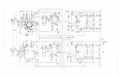
Voltage measurements taken last night are in red, factory specs in black. There is a -60mV disparity at voltage measurement taken at Q205 collector which is the input to PB-1080 output board.
The disparity between the factory 1.18V on either side of the bias transistor Q303 on the left channel is because the outputs are not biased correctly?
The left channel bias pot is below 70mA it is supposed to be biased at 150mA but when trying to set bias on the left channel oscillation occurs. So it is currently adjusted to lowest bias position.
Attachments
Let me know which are the voltages you are powering the 5M21 with, so I can load it on the simulation and tell you what all the values should be. Specifically for your voltages.
The factory voltages re +/-67 regulated and +/-61v unregulated. So it's no use to check your voltages if you don't know what they really should be.
The factory voltages re +/-67 regulated and +/-61v unregulated. So it's no use to check your voltages if you don't know what they really should be.
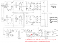
Measured factory voltages provided for PB-1081. The base of Q503 factory provided voltage should be -0.17V. The emitter factory provided voltage is 0.7V. The measured measured voltage on Q503 base is +2V. The measured voltage on the emitter is 0.8V. Its a PNP so it is supposed to be on, with +2V on the base is keeping it off. Don't exactly
know what Q501, Q502, and Q503 are doing but one might assume they are part of establishing the feedback signal since they are tied into the circuit. There are 5 electrolytic caps in this circuit area so have ordered replacements.
know what Q501, Q502, and Q503 are doing but one might assume they are part of establishing the feedback signal since they are tied into the circuit. There are 5 electrolytic caps in this circuit area so have ordered replacements.
Measured factory voltages provided for PB-1081. The base of Q503 factory provided voltage should be -0.17V. The emitter factory provided voltage is 0.7V. The measured measured voltage on Q503 base is +2V. The measured voltage on the emitter is 0.8V. Its a PNP so it is supposed to be on, with +2V on the base is keeping it off. Don't exactly
know what Q501, Q502, and Q503 are doing but one might assume they are part of establishing the feedback signal since they are tied into the circuit. There are 5 electrolytic caps in this circuit area so have ordered replacements.
Not factory voltages, the power voltages. What voltages did you use when you made your measurements?
Replaced electrolytics on PB-1081. Protect relays will not latch after cap replacement. Realize that before capacitor replacement that after 4 minutes or so the relays would unlatch. Q506 determined to be open base to emitter. Purchased 2SC2240 to replace the 2SC734. Waiting to recieve transistor.
Last edited:
Why use an obsolete and hard to find not fake 2SC2240, instead of a legitimate replacement like the KSC1845?
KSC1845FTA ON Semiconductor / Fairchild | Mouser
KSC1845FTA ON Semiconductor / Fairchild | Mouser
Purchased 10pcs USA seller Toshiba 2SC2240 for $2.99. This transistor being part of the DC protect circuitry doesnt seem all that important. Decided not to spend $4.99 in shipping alone from mouser. If it fails again the relays wont latch and it is an easy replace. Also have nine spares.
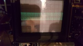
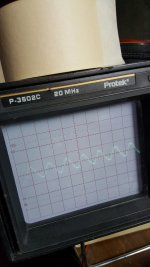
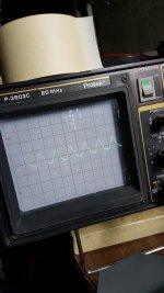
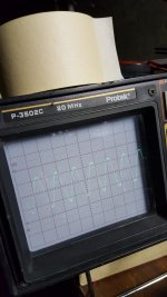
have determined the oscillation is a 1.8mhz 200mv p-p
image is a measurement at left channel output
this is with no input signal and no output load.Gain pots are at a minimum
image of oscillation. 10X probe. 10mV/div and2us/div.
image is a measurement at left channel output
this is with no input signal and no output load.Gain pots are at a minimum
image of oscillation. 10X probe. 10mV/div and2us/div.
Attachments
Last edited:
went upstream....consistent appearance of oscillation on output board.
Went to DML pin11, base of Q201, and found no evidence of oscillation.
Went to DML pin9, base of Q202, and found oscillation.
Went to emitters of Q201 and Q202 and found evidence of oscillation.
Went to DML pin11, base of Q201, and found no evidence of oscillation.
Went to DML pin9, base of Q202, and found oscillation.
Went to emitters of Q201 and Q202 and found evidence of oscillation.
Attachments
Last edited:
went forward with swapping the feedback and signal out on the PB1079 input card , right to left and left to right. The oscillation followed the leftchannel side of PB1079. So something on the left channel input board is causing the oscillation.
Have it isolated so I feel I am getting somewhere.
Also know the output board is good.
Have it isolated so I feel I am getting somewhere.
Also know the output board is good.
no both right and left are new DML's, Hans Hilberink modules.
Sometime ago I swapped the new modules and the oscillation did not follow.
Even swapped in the OEM DML module...was able to plug them into the sockets used to plug Hilberink's DML's in to. Oscillation still present.
Sometime ago I swapped the new modules and the oscillation did not follow.
Even swapped in the OEM DML module...was able to plug them into the sockets used to plug Hilberink's DML's in to. Oscillation still present.
- Status
- This old topic is closed. If you want to reopen this topic, contact a moderator using the "Report Post" button.
- Home
- Amplifiers
- Solid State
- Luxman 5M21