Practically all serious amps now carry multiturn bias trimpots, instead of carbon types.
It does allow more precise adjustment, and I haven't heard any reports of the new types failing. In fact it would be much better to provide a small mod on the pcb and leave the pot on one side of the divider, instead of it splitting the bias transistor base voltage. It would be safer for the amplifier.
That is the way I have simulated the 5M21 clone, and it works perfectly. Some would say it's much even better, audio quality wise, to replace the pot with single resistors.
It's a good move to reflow the solder joints. Hopefully that solves your oscillation problem.
The original trimpots, both for bias and DC offset, are one-turn pots. Certainly carbon.
Cermets would be better pots, but they are still one turn. Multiturn allows fine adjustment and are wire-wound pots, not cermet or carbon.
The question to deal here is eventual pot-malfunctions and precision adjustment. On both things the multi-turns are much better.
Cermets would be better pots, but they are still one turn. Multiturn allows fine adjustment and are wire-wound pots, not cermet or carbon.
The question to deal here is eventual pot-malfunctions and precision adjustment. On both things the multi-turns are much better.
Here are the Bourns multi.
http://www.mouser.com/ds/2/54/296-776415.pdf
Pick the model you want, an affordable one can cost $2.41 or less. They are cermet.
http://www.mouser.com/ds/2/54/296-776415.pdf
Pick the model you want, an affordable one can cost $2.41 or less. They are cermet.
Had to reconsider my recommendation for using a multi-turn pot for bias adjust.
I was just reading an old thread here on a Rotel 820 mods, and it was suggested that the fact that trimpot handles current dictates that a multiturn pot might not be ideal there. A high quality single-turn type would be better.
Also looked again at how Luxman had connected the bias pot, and there is no risk if the pot fails. In fact it made me think that, once you get to a bias setting, replacing it with a resistor might be good idea, it would be a simple mod and might improve audio quality.
carlmart, it can not be stated enough I am in training on chasing this oscillation issue. The other day I decided to try to oscope through the driver board PB-1079, compare R channel to L channel .
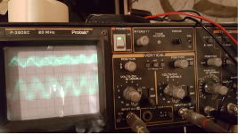
No signal in and bias level on L channel set low so no oscillation should be ocurring. Hung X1 probes on signal out PB-1079, Q205 collectors, image attached. Channel A top signal is right channel out, Channel B left signal out. Interesting that there is a signal difference in amplitude.
Played for some minutes and powered down and came to the conclusion that hanging the probes on the signal output of PB-1079 caused oscillation on the output transistors, they were warm.
Last night decided to start reflowing all connections starting on PB-1079 driver board on the left channel. Reflowed beta (feedback components) and input signal to pin 2 of DML01. Still have lots of reflowing to do.
Attachments
OK, maybe it´s not related to your oscillation source, but let me tell you about one oscillation I found on my 5M21 LTSpice simulation.
The strange thing is I had been playing with the 5M21 for several weeks, and I never had that. The fact is that I had not been checking the LTP stage, and the oscillation happened when simulating injecting 20KHz.
And there it was: a large spike mounted on the sine wave.
Keantoken was the person that helped me found the way to solving the problem.
Perhaps you wish to try if this solves your problem.
As an attempt to possibly isolate the issue to the driver board PB-1079 or the power output board PB-1080 couldnt the right and left signal input and feedback signals be swapped on the power board PB-1080? If the oscillation swaps channels would not that isolate the issue to the driver board.
Of course, swapping the boards would help see better where the problem is.
As I see you have injected a sine signal into the amp. Check the signal on the LTP out on both channels. That would be R205 and R206 (15K), on the side opposite the DC rail.
If you can, show me how the signal looks.
As I see you have injected a sine signal into the amp. Check the signal on the LTP out on both channels. That would be R205 and R206 (15K), on the side opposite the DC rail.
If you can, show me how the signal looks.
Calmart hooked X10 probe on pins 9 and 11 of right and left DML1 modules. Injected 400hz 0.7V input signal. Each had sinewave at those points as gain was increased. When gain turned to maximum on the left channel lost signal trigger, sinewave still there but not triggering properly. This does not occur on right.
Did not leave at maximum gain fore more than a second. Just swung gain pot from min to max back to min.
Monitored outputs and they were not getting warm.
The amp went into protect while probe was on right channel but after removing probe and input signal it came out of protect. Do not know what that was all about.
Calmart, that oscope image from thread #73, 8/8, there is no input signal. That image taken using X1 probes are the right and left channel PB-1079 outputs to PB-1080. Amp idling with gain pots at minimum. The vertical scale is .5V/div.
This will be reset up again using X10 probes to see what it looks like.
This will be reset up again using X10 probes to see what it looks like.
Last edited:
- Status
- This old topic is closed. If you want to reopen this topic, contact a moderator using the "Report Post" button.
- Home
- Amplifiers
- Solid State
- Luxman 5M21