That's some bad news.
So are they actually being disconnected like this?
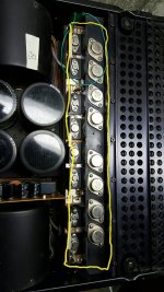
Yes the output leads are not soldered into the PCB. Remove screws and the output can be removed.
If the mounting screws in the outputs are removed, it disconnects the rail voltage from the collector. If the rail voltage is no longer present on the channel output you know that output is shorted allowing rail voltage on to the channel output.
Any sign of excessive current?
No signs of overcurrent. As stated reflowed two solder connections on left channel PB-1080. These were done from the back side of the board, do not know what happened to the top side of PB-1080. Now have short from rail voltage to right channel output. Strange thing. Could have created some solder balls on trace side when those joints were reflowed. Had amp on its side vertically.
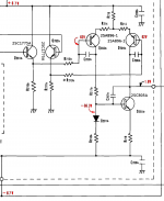
Do you get an actual short (measurable when powered off with transistors disconnected), or what kind of resistance do you see? It wouldn't be a bad thing to have solder balls floating around inside the amp, of course, but the problem could also be another bad joint or even a cracked PCB. For example, having no connection between the two boards could have the same effect. Verify continuity between Q205 E and Q301 B assuming you can get to them.
Last edited:
Can you get to the connection between PB-1079 (the voltage amplifier board with the DML on it) and PB-1080 (the output board)? Would be interesting to see what you get there.
Which connection? The audio signal connection?
If the output stage works, it should be about -60 V. Otherwise Q201 may be open or something.
The rail voltages are all present approx. -62V and +62V.
Problem now is the -62V is shorted to the right channel output which is allowing the speaker DC protect relay to stay open.
Hang on, was the oscillating channel the one with the new DML in it...?
Both channels have had Hans Hilberink's aftermarket DML's installed.
Do you get an actual short (measurable when powered off with transistors disconnected), or what kind of resistance do you see?
Measures approx 200kohm between each rail and the output path with transistors in circuit.
Can you get to the connection between PB-1079 (the voltage amplifier board with the DML on it) and PB-1080 (the output board)? Would be interesting to see what you get there. If the output stage works, it should be about -60 V. Otherwise Q201 may be open or something.
sgrossklass, Good afternoon....had a few minutes before I left for work. Decided to put it on a dim lit bulb until diagnosed.
Interestingly enough it acts proper on the dim light bulb tester. Probably lucky...whatever is going on it doesn't allow high current flow.
Did check output from PB-1079 to PB-1080 and measured -57V. So you were suspicious of this. Would be interesting to determine if this is being caused by PB-1079 or PB-1080.
As I said, the output stage by itself would probably drift off with its input left open. If you can see a way to connect the signal input to PB-1080 on the faulty channel to ground (maybe chassis), please try that and measure output DC offset again. Should be much closer to zero now, maybe a volt or so. If so, the output stage is OK.
Another thing I would like to try - assuming you can find a way to do it - would be disconnecting the feedback (the line that goes to the RC in the "beta circuit" section) from the output and reconnecting it at the PB-1079 output instead. Then you can measure offset there. If feedback works, it should be essentially zero - I presume it's not.
Another thing I would like to try - assuming you can find a way to do it - would be disconnecting the feedback (the line that goes to the RC in the "beta circuit" section) from the output and reconnecting it at the PB-1079 output instead. Then you can measure offset there. If feedback works, it should be essentially zero - I presume it's not.
Sgrossklass, hi.
There was a component on the bottom of the PB-1079 board connecting two of the DML pins. It was in shrink tubing, not sure if this left the factory that way? A trace that would have connected the two pins was cut through and this component now spanned the cut through, both channels are similar. On the right channel the one that has rail voltage on the output one of the leads of this component had become detached. Before reconnecting could not get the +62.4V at the input of Q201/Q202. After reconnecting the lead required voltage drop is present. Checked most of the voltages on PB-1079 and everything seems to be as required other than measuring +64V at the collectors of Q204/Q205. This is with the signal output wire between PB-1079 and PB-1080 disconnected. The schematic shows that should be less than 2V.
Also have already disconnected the feedback from PB-1080 to PB-1079 since it was measuring high voltage as well.
Sgrossklass, grounded PB-1080 input to right channel, still have feedback disconnected. You are correct with input grounded the DC on output is just a volt or so.
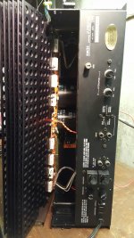
This leaves me the input card PB-1079 to diagnose. Thanks for the suggestion i was just tearing into the amp for possible work to power card PB-1080. Figured out how to remove PB-1080 and heatsink. Might be helpful as we move along.
This leaves me the input card PB-1079 to diagnose. Thanks for the suggestion i was just tearing into the amp for possible work to power card PB-1080. Figured out how to remove PB-1080 and heatsink. Might be helpful as we move along.
Attachments
Last edited:
As I said, the output stage by itself would probably drift off with its input left open. If you can see a way to connect the signal input to PB-1080 on the faulty channel to ground (maybe chassis), please try that and measure output DC offset again. Should be much closer to zero now, maybe a volt or so. If so, the output stage is OK.
Did this as directed and it came out of protect. Measured .6V DC output.
Another thing I would like to try - assuming you can find a way to do it - would be disconnecting the feedback (the line that goes to the RC in the "beta circuit" section) from the output and reconnecting it at the PB-1079 output instead. Then you can measure offset there. If feedback works, it should be essentially zero - I presume it's not.
Leave the input of PB-1080 grounded. Then take the feedback from right channel PB-1080 and connect it to the right channel output of PB-1079?
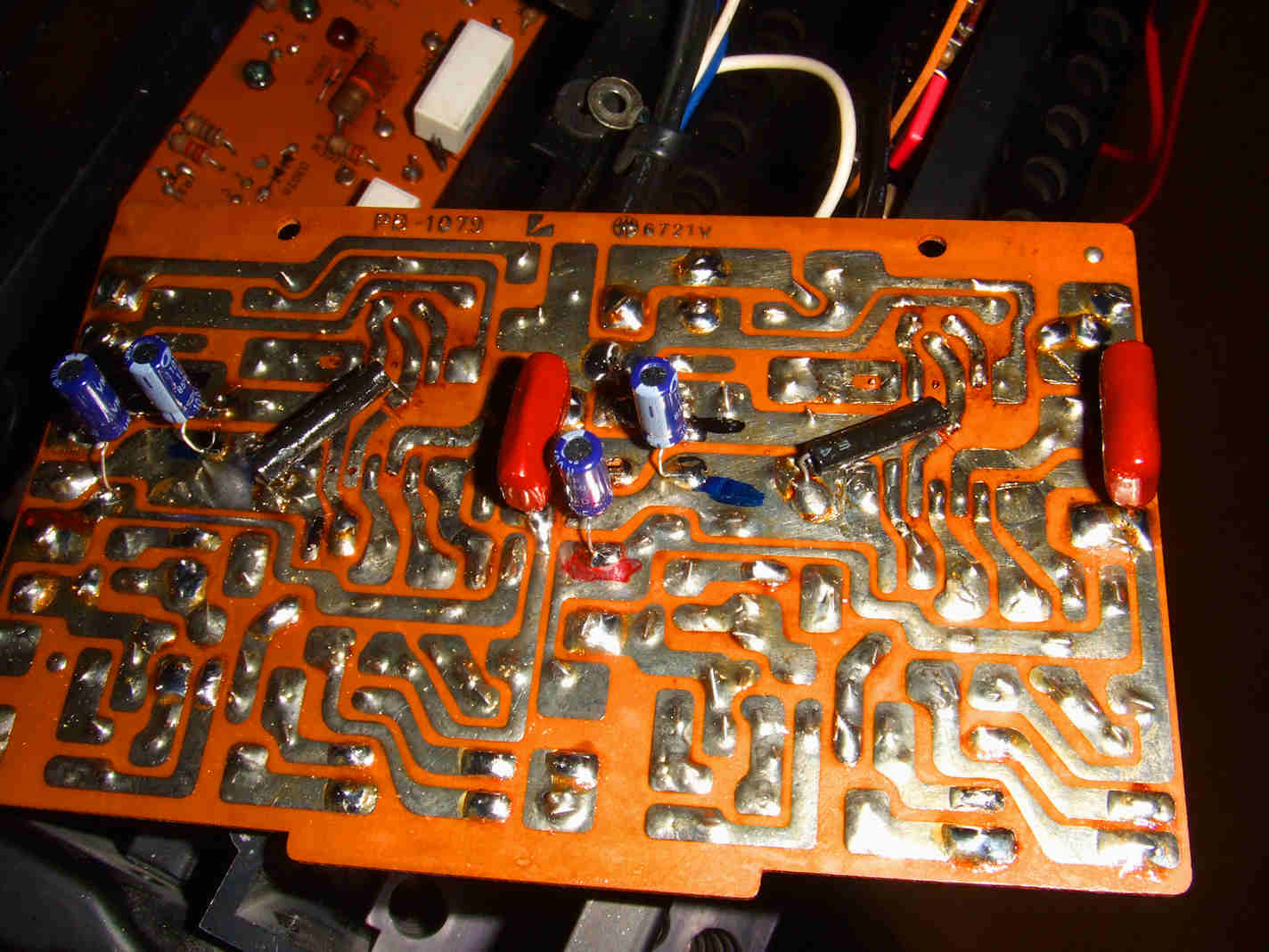
Image of backside of PB-1079 showing the component and the trace that has been cut. Looking at it now the component doesnt span the cut trace. The trace cut is between pins 5 and 12. The sleeved component which measured 120kohm in circuit spans pins 5 and 2.
Attachments

Last edited:
Yep.Leave the input of PB-1080 grounded. Then take the feedback from right channel PB-1080 and connect it to the right channel output of PB-1079?
PS: Text edited into quotes is annoying and hard to find, please just add some [ /quote ] and copy/paste [ QUOTE= bla, 1234 ] as needed.
SSgrossklass, there is +64V at the output of PB-1079. The output should measure 1.8V. So connect the feedback to the +64V?
Shouldnt feedback be close to 0V?
Shouldnt it measure 1.8V there before connecting anything to the output of PB-1079.
With the input of PB-1080 grounded DC offset measures 0.6V. The feedback measures 0.4V.
Shouldnt feedback be close to 0V?
Shouldnt it measure 1.8V there before connecting anything to the output of PB-1079.
With the input of PB-1080 grounded DC offset measures 0.6V. The feedback measures 0.4V.
Last edited:
[/quote]
If that's the spot that the collector of Q205 connects to, yes, that's correct. Voltage at this spot with the feedback open is generally hard to predict, except it tends to slam into one of the rails.
With the input of PB-1080 grounded I did reconnect the feedback measuring .4V to the RC beta circuit. The output of PB-1079 stayed at high voltage.
So are you still advising to connect the feedback to the collector of Q205(PB-1079 signal out) while the input of PB-1080 is grounded?
Last edited:
- Status
- This old topic is closed. If you want to reopen this topic, contact a moderator using the "Report Post" button.
- Home
- Amplifiers
- Solid State
- Luxman 5M21