just purchased a Luxman 5M21 amp that I chased for several years before it finally got sold to me. It was purchased non functioning. I had read some time back about the DML modules being the achille's heel and interestingly enough when the box was opened a loose removed DML module was inside with the amp. Pulled the cover off the bottom of the amp and observed the input board was missing one of its DML modules. It must have been determined to be bad and it was at the time when these were not available.
Both DML modules replaced with Hans Hilberink's current replacements.
Amplifier powered up after replacement of modules. Yay.
Zero'd DC offset, played some audio at low volume sounded good but it seemed to be running warm more so on the left channel.
Set up to check bias and was able to decrease bias on right channel to 150mA.
Bias on left channel:
On the bias trim when adjusting downwards it gets to approx 200mV it jumps to 70mV when adjusting back up it jumps to 200mV.
when set to as close to 200mV or so drifts down to 50-70mV
Above 200mV drifts upward to 350mV before the amp was powered down.
")
checked functionality of the bias variable resistor (1kohm) it is functioning correctly.
Back on luxman 5M21. Bias needs to be able to be set to 150mA. Was able to adjust bias on right channel. Bias on left channel:
On the bias trim when adjusting downwards it gets to approx 200mV it jumps to 70mV when adjusting back up it jumps to 200mV.
when set to as close to 200mV or so drifts down to 50-70mV
Above 200mV drifts upward to 350mV before the amp was powered down.
Set up the Luxman 5M21 for no load oscope test. Put a signal through it, square wave, 400Hz, 1V and looked at the input versus output. Without knowing how or what to look for when looking for oscillation, the input matched the output other than the output square wave wasnt flat as the input signal being supplied. There was a slight decrease in the amplitude of the output square wave from the rise to the fall. It was the same on both channels. Not sure if it was more of a result from the test set up.
Checked the voltage measurements of the bias transistor. The left channel, this is the one the bias current is drifting,
Bias Q left base 583mV
col 1.16V
em -1.3V
Bias Q right base 405mV
col 1.29V
em -1.11V
Realizing that the base voltage on the Bias Q can be set to whatever the variable resistor is set to the voltage measurements are probably of no value.
I guess I am interested in determining if the base voltage of the Bias Q on the left channel was drifting causing the current to drift.
Considering replacing the left channel bias xistor so it can be ruled out. It is a 2SC1904 and am considering chasing down a NTE373 to replace it with...the 2SC1904 can always be put back if it is good.
Attachments
Last edited:
Bad pot or oscillating amp. Since you have a scope you could hook that up to the output and check for the latter.On the bias trim when adjusting downwards it gets to approx 200mV it jumps to 70mV when adjusting back up it jumps to 200mV.
Sgrossklass, i have not observed oscillation on an amp. I have no professional tech experience just hands on and alot of help from you guys. I work as much as i can with anatech. He mentioned oscillation as a possibility. Do not have that much hands on experience with the oscope but always willing to learn. How closely does the input signal have to be scrutinized to determine oscillation.
As stated i put a 400hz, 1V square wave in and a similar square wave came out other than the amplitude of the square wave decreased from rise to fall. It was the same on both channels. Could that be more of a set up issue? Will set back up with oscope and start snapping some images. But what are we trying to see when it comes to oscillation? Bob
As stated i put a 400hz, 1V square wave in and a similar square wave came out other than the amplitude of the square wave decreased from rise to fall. It was the same on both channels. Could that be more of a set up issue? Will set back up with oscope and start snapping some images. But what are we trying to see when it comes to oscillation? Bob
A "sagging" square wave indicates a highpass, typically tone controls or coupling cap (potentially a bad one if the effect is too severe).
Checking for a bad pot might actually be easier, observe whether there is a jump in resistance as you turn it with the power off.
Checking for oscillation:
Turn up bias until it goes into the >200 mV region. Initially set scope for 5 V/div or so (just so you don't accidentally fry the vertical). Slowly turn up scope sensitivity. What you should be seeing is a bit of noise as you get down into the 5-10 mV/div region, maybe some low-frequency components. Decrease time base to see whether there's anything in the MHz range going on. Global oscillation tends to be around 1 MHz (+/-), local oscillation in the output stage could be at dozens of MHz.
If you see anything suspicious, reduce bias into the <70 mV range to see whether it goes away. Best reset scope sensitivity for this.
Last edited:
sgrossklass thanks for your reply.
made the variable resistor check already. Didn't appear to be any anomaly in resistance measurements over the entire 1K range.
will set up oscope and observe output signal in a manner as you have layed out. Will share observations with some digital pics.
as stated earlier the sagging is similar on both channels.
regards Bob
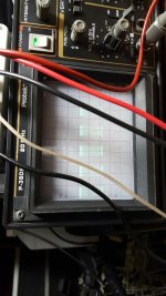
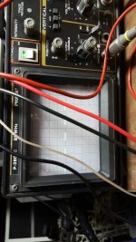
Hooked scope up and voila...there is oscillation. Images are of the top of the square wave, 500hz, .2V div, 1ms div.
Second image is with bias below 70mv. The first image showing the oscillation is above approx 200mV.
So what do I do next?
Second image is with bias below 70mv. The first image showing the oscillation is above approx 200mV.
So what do I do next?
Attachments
The amps output stage has not had any repairs. I have observed a few solder joints that do not look very good. Specifically one on one of the outputs on this channel, large void in the solder joint. I have not done a thorough inspection yet. Will get on that.
Which capacitor is the Miller capacitor?
Wanted to point out that the waveform is not sagging. The vertical input coupling was set on AC. Switched to DC and waveforms were not sagging.
Which capacitor is the Miller capacitor?
Wanted to point out that the waveform is not sagging. The vertical input coupling was set on AC. Switched to DC and waveforms were not sagging.
Last edited:
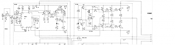
Had a look at the schematic now. The decoupling caps are all film caps, those are not too likely to fail - though it certainly is possible. If you've got some 100n and 1µ film caps rated at least 100V that you could hook up in parallel for a test, that would certainly be worth a shot. (C208/209 are 1µ, C204 is a 100n, as are C304/305. All kinda small. There's also C201 which is a 47n.) If the DML module had been removed, what about C202 (100p)? Also inspect the ground connection to the boards in question.
You'll also want to inspect the Zobel network, R512 (4.7R 5 W) and C505 (220n).
I don't think you'd see high-frequency oscillation like that if some of the big 15000µFs were shot, though the power supply certainly is seperate for left and right channels. If your scope will support a good +/-60 V when AC coupled (or maybe when using a 10:1 probe), you could look at supply ripple for both channels and note down how much you see on positive and negative rails.
Interesting, the (bypassable) input caps are a pair of antiparallel tantalums. Would be interesting to know how leaky those might be these days. I guess the idea was that they should last a long time, so the designer didn't trust regular low-leakage electrolytics, and the antiparallel circuit would eliminate a lot of the distortion (tantalums are pretty crummy). Why they didn't use films in the first place is anyone's guess.
For a fun exercise, you could run a resistor of at least a megohm from the nearest convenient negative voltage supply to the midpoint between the tantalums for each channel, that should reform 'em.
Last edited:
sgrossclass, amp will not come out of protect mode now. Reflowed the transistor socket leads, on one of the PNP output transistors, the solder connections on the printed circuit board.
Removed the output from the socket and tested it. The output is good.
Will need to figure out how to dissassemble this so the top side of the power board can be visually inspected.
Removed the output from the socket and tested it. The output is good.
Will need to figure out how to dissassemble this so the top side of the power board can be visually inspected.
That's some bad news.
So are they actually being disconnected like this? Any sign of excessive current?
Can you get to the connection between PB-1079 (the voltage amplifier board with the DML on it) and PB-1080 (the output board)? Would be interesting to see what you get there. If the output stage works, it should be about -60 V. Otherwise Q201 may be open or something.
If the output stage looks fine, please also measure the voltage difference between DML pins 2 and 7. Should be very small, as in single mV. If not, check the feedback resistors (the ominous "beta circuit"), you might have an open there. Same between bases of Q201 and Q202, and Q203 and Q204. With some bad luck the new DML module has let out the magic smoke already, in which case you would have to investigate which external factors are killing DMLs there.
Hang on, was the oscillating channel the one with the new DML in it...?
Last edited:
- Status
- This old topic is closed. If you want to reopen this topic, contact a moderator using the "Report Post" button.
- Home
- Amplifiers
- Solid State
- Luxman 5M21