Now this thread really caught me. I simply had to hook up an LM and do some real-world measurements.
Please have a look at the results here: LM317 regulator under test
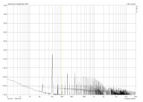
I've attached an overview of the tested circuits and the noise results here. To sum up, I'd say that "no TL431 is best", at least noise-wise. A simple Zener is at least as good, partially even better, while a simple cap outperforms both of them. Regarding the load step response, it is better to put a cap between TL431 cathode and TL431 ref instead of between LM317 out and TL431 ref.
Something about the TL431 to be aware of is that there are a ton of different variants available, from several manufacturers.
From post #28 :
You could go with the Exar SPX2431AM, it is similar to the TL431 but with significantly reduced noise compared to the standard TL431.
Standard TL431 is around 120nV/hZ at 1K and the SPX2431AM is 40nV/hZ at 1K.
The NCP431 looks to have around 600nV/hZ at 1K according to the dataheet, that is downright terrible. Surely that must be an error?
Which basiacally means that it is important to use the right TL431 variant.
The difference in noise from the low noise 40nV/Hz EXAR2431AM to the very high noise 600nV/Hz NPC431 is absolutely HUGE.
Another thing, the 400 Zener reference version indeed looks to be slightly worse than the standard capacitor 002 version, but in some cases it might overall be a better option, if for example you need very high, low frequency rejection. The Zener reference should give improved ripple rejection all the way down to DC. Sure, it is a special case but there might be someone who needs it.
Last edited:
Pergo, any idea how I could do this? I don't own a signal generator, so what about using the soundcard as generator with an amp for the muscles and a big C to couple it in? What about the levels? And then there'll be no MHz's of course...
Check out Walt Jung's website -- Home -- he sets the gold standard for measurement of noise, PSRR and output impedance.
Link to his articles: References & Regulators WaltsBlog
SGK, you're welcome
The traces in red are the ones (in the second diagram I posted here), but please have a look at LM317 regulator under test preamp.org, there you'll find more detailed information, like step response and actual recorded flac's for your personal enjoyment.
Got it thx. Horowitz would recommend a resistor is added to the source of the JFET. I would be interested - if you have the inclination - to see your tests with this added (with and without C3).
But you need a signal generator with offset regulation to have fine tuning of output.
Unfortunately I don't know how to get one here on my little island, except for buying one. My wife will kill me if I do
.But what about reducing the 1000uF filter cap to smaller values? Still no HF data, but maybe it has some merits?
Something about the TL431 to be aware of is that there are a ton of different variants available, from several manufacturers.
Just looked what my "ET TL431" might be and found this one: http://www.estek.com.cn/UploadFile/Download/201204101424163565.PDF
Datasheet simply states "low output noise voltage" but no data, so I guess it'll be more on the noisy side.
The zener version (400) is what I'm actually using in my preamp.
Check out Walt Jung's website -- Home -- he sets the gold standard for measurement of noise, PSRR and output impedance.
Thank you, Jack. I've had a look at Walt's site a couple years ago, but I'll dig through it again to see if I can come up with something for PSRR.
Got it thx. Horowitz would recommend a resistor is added to the source of the JFET. I would be interested - if you have the inclination - to see your tests with this added (with and without C3).
Sure, I'll do it
. Probably on the quick right now, and thoroughly again when I've found a way to check PSRR, too.Guess what, I'll have to do all this measurements again
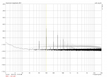
!Looking over the original circuit of my preamp (built in 2009 and rarely used since then), I stumbled over the gain of 40 that I measured at 50Hz. Had I done a spectrum analysis with white noise, I would have noticed it much earlier... The preamp was supposed to have a gain of 40dB, not 40!
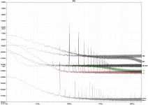
Well, **** happens. So I reviewed the circuit today and additionally reduced the feedback network by an order of magnitude for even better noise performance. Now the sub-20Hz spectrum actually looks like you would expect it from an LT1028. Did a quick analysis of the last circuit I tested (the 302) to show you the difference it makes (new in black, old in grey).
Attachments
... if for example you need very high, low frequency rejection. The Zener reference should give improved ripple rejection all the way down to DC. Sure, it is a special case but there might be someone who needs it.
About the lowest dynamic impedance Zener diode you can buy is the 1N5339, at 1.0 ohms. Integrated circuit replacements for Zeners, so-called "shunt voltage references" have a dynamic impedance of 0.2 ohms, a factor of 5 times lower than the best Zener diode, and a factor of 30 times lower than the most commonly used Zeners. So if you need very, very high rejection of low frequency noise, you can replace the Zener with a shunt voltage reference IC. One example is the TL431. Post #58 of this thread, shows a schematic.
Last edited:
But what about reducing the 1000uF filter cap to smaller values? Still no HF data, but maybe it has some merits?
You've only LF response. Those difference should be greater at HF.
But you can try reducing input cap and see 50-100Hz rejection difference between reality and sims
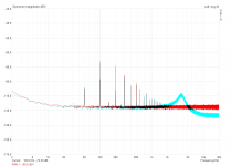
Don't get this resistor variant to work . Added 100R for the first measurement you see here (the cyan trace). Looks weird so I measured the current: >13mA, like without the resistor. Hm. Substituted a 500R pot, >13mA at every position. Tried some 4K, still >13mA. Eventually gave up on it .
. Added 100R for the first measurement you see here (the cyan trace). Looks weird so I measured the current: >13mA, like without the resistor. Hm. Substituted a 500R pot, >13mA at every position. Tried some 4K, still >13mA. Eventually gave up on it .Attachments
So if you need very, very high rejection of low frequency noise, you can replace the Zener with a shunt voltage reference IC. One example is the TL431. Post #58 of this thread, shows a schematic.
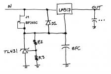
Mark, what about using my 13.??mA BF245C instead of the LM334 in the schematic you supplied? If this is almost as good, I'd happily try it.
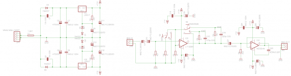
If anyone is interested in or likes to make some suggestions, here is the schematic of the preamp I'm currently using.
Attachments
Don't get this resistor variant to work
This is what i meant.
An externally hosted image should be here but it was not working when we last tested it.
Mark, what about using my 13.??mA BF245C instead of the LM334 in the schematic you supplied? If this is almost as good, I'd happily try it.
Yes you can use a BF245C NJFET, whose IDSS is 13 milliamperes, to bias the shunt voltage reference integrated circuit. Just be certain to bypass the IC with at least 33 microfarads. This ensures stability, filters noise, and lowers impedance at high frequencies.
B.F.C. is an acronym for Big Fadjective Capacitor; i.e., any capacitor whose optimal value is infinity. The bigger the better.
Remember that Vout = 1.25 + (2.5 x (1 + (R2/R3)))
See attached schematic diagram.
Attachments
Last edited:
Sounds good! Looks like this is going to be a long weekend .
The BFC will be 100uF and probably the 10k trimmer will be R2/R3.
I calculated R2 = 68k and R3 = 15k for approx. 15.08V but I'm not sure if I have them handy. 47k and 10k would be close with 15.5V, then.
By the way, would all this also be possible with the LM337?
Pergo, what are you aiming at? I for one run my tests at 245mA or 70mA and not without any load. For a practical reason, you could add a simple power-good-LED with a resistor to every LM in case it may become unloaded otherwise.
.The BFC will be 100uF and probably the 10k trimmer will be R2/R3.
I calculated R2 = 68k and R3 = 15k for approx. 15.08V but I'm not sure if I have them handy. 47k and 10k would be close with 15.5V, then.
By the way, would all this also be possible with the LM337?
Pergo, what are you aiming at? I for one run my tests at 245mA or 70mA and not without any load. For a practical reason, you could add a simple power-good-LED with a resistor to every LM in case it may become unloaded otherwise.
Don't get this resistor variant to work
I wonder if your results aren't just consistent with the Spice simulation but with a wider frequency band. Using the circuit I posted above.
With R1 = 0
An externally hosted image should be here but it was not working when we last tested it.
With R1 = 28
An externally hosted image should be here but it was not working when we last tested it.
Or am I smoking something?
LTSpice would suggest adding a cap between the J309/310 source and ref of the TL431 would not be a good idea:
An externally hosted image should be here but it was not working when we last tested it.
Last edited:
Getting nothing done . Weather is getting better each day, so I'm supposed to help my wife with the garden.
Walt used a discrete regulator for his PSRR-tests to supply the DUT with 18V and 1Vpp AC from 20Hz-200kHz and a 150mA resistive load. He also writes this:
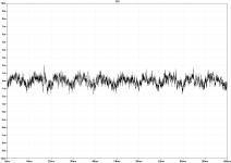
I'm about to hook up such an LM317-rig for its simplicity and test if it's sufficient for my needs. Ultimately I'm only able to test up to 96kHz with my soundcard, which is performing worse and worse from 30kHz onwards. This isn't even remotely enough to match Walt's results, but should be sufficient for a direct comparison between the different circuits.
Here's a quick comparison of the noise floor using 48k vs. 196k sampling.
. Weather is getting better each day, so I'm supposed to help my wife with the garden.Walt used a discrete regulator for his PSRR-tests to supply the DUT with 18V and 1Vpp AC from 20Hz-200kHz and a 150mA resistive load. He also writes this:
Walt Jung said:Some initial positive rail regulator testing was accomplished using a 317-type regulator as an 18V regulator/driver, with the AC test signal coupled into the normally grounded C-adj capacitor. While much simpler than the discrete circuit driver (...), this setup was not completely satisfactory, since spurious resonances occurred at certain frequencies.
I'm about to hook up such an LM317-rig for its simplicity and test if it's sufficient for my needs. Ultimately I'm only able to test up to 96kHz with my soundcard, which is performing worse and worse from 30kHz onwards. This isn't even remotely enough to match Walt's results, but should be sufficient for a direct comparison between the different circuits.
Here's a quick comparison of the noise floor using 48k vs. 196k sampling.
Attachments
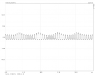
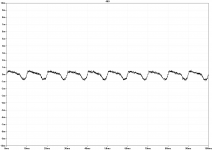
Seems like the LM317-approach is not working. I've made a quick test with several frequencies and the results mostly look rather bad. The sine gets badly distorted by the first 317 already and what's coming out of the DUT looks even worse. Attached is the result of 1kHz 1V-pp.
Not sure if I'm willing to build a discrete super-reg like Walt did; perhaps I'll try a DC-coupled chipamp instead, someday.
Anyhow, I'd need a software package (affordable; preferably free) that is able to do sine sweeps and perform the necessary calculations. Otherwise I'll have to do it all by hand using ARTA (which does frequency response measurements with pink or white noise instead of sweeps).
Not sure if I'm willing to build a discrete super-reg like Walt did; perhaps I'll try a DC-coupled chipamp instead, someday.
Anyhow, I'd need a software package (affordable; preferably free
) that is able to do sine sweeps and perform the necessary calculations. Otherwise I'll have to do it all by hand using ARTA (which does frequency response measurements with pink or white noise instead of sweeps).Attachments
While doing most of the measurements again, I somehow managed to kill the TL431, so I couldn't redo pergo's version or test mark's at all . Will fix this tomorrow.
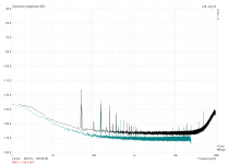
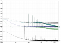
Anyhow, here's another crowded overview of the circuits I tested this evening. This time the scale in dBV should be accurate (I tested it beforehand). For better readability I create the graphs using LTspice from now on. This allows me to keep the same scale for every measurement each time. Added bonus is that I can supply you with the RAW-files for your personal delight.
An update to my website with the new graphs for transient and step response will follow soon.
. Will fix this tomorrow.Anyhow, here's another crowded overview of the circuits I tested this evening. This time the scale in dBV should be accurate (I tested it beforehand). For better readability I create the graphs using LTspice from now on. This allows me to keep the same scale for every measurement each time. Added bonus is that I can supply you with the RAW-files for your personal delight
.An update to my website with the new graphs for transient and step response will follow soon.
Attachments
Finished.  Finally...
http://preamp.org/diyaudio/lm317-regulator-under-test
Mark, your circuit is not performing well on my bench (#320, colored in teal). Maybe this is a good example of the difference between simulation and reality? Or do I need a better performing TL431 to see the real benefit of this topology?
Looking over the waveforms, I still think the Zener-version (#400) is still performing best overall.
Finally...http://preamp.org/diyaudio/lm317-regulator-under-test
Mark, your circuit is not performing well on my bench (#320, colored in teal). Maybe this is a good example of the difference between simulation and reality? Or do I need a better performing TL431 to see the real benefit of this topology?
Looking over the waveforms, I still think the Zener-version (#400) is still performing best overall.
Attachments
- Status
- This old topic is closed. If you want to reopen this topic, contact a moderator using the "Report Post" button.
- Home
- Amplifiers
- Power Supplies
- LM317+TL431, really?