Yes I hope the solid state disk drive is able to function correctly when its supply voltage changes by (120+10) millivolts over the course of 100 seconds, as the temperature of the ambient air around the TL431 increases by 120 degrees Celsius. The TL431 won't self heat very much at only 30 milliwatts dissipation.
The datasheet say "over the temperature range" so the drift must be divided by the range. 130mV max are over 190°C range so the effective change from, for example, 20°C and 60°C is only 27mV maximum.
Absolutely good.
If you want some compensation you can add a diode in series with R2 (in your circuit).
The diode dropout will decrease as temperature rises, with typical -2mV/°C.
If you study a correct place for the diode, you can perfectly compensate drift.
But it's an overkill")
SDDs have internal regulator as well, because logic is powered by 3.3V or something below (like 1.9V or 1.5V).
They enter with 5V because standard cable pinout and adaptors has only 5V and 12V section (due to standard HDD types and 4pin molex plug).
New SATA power cables have 3.3V as well.
So it's a no-problem. As it's useless use a pre-regulator in a SSD device.
Absolutely good.
If you want some compensation you can add a diode in series with R2 (in your circuit).
The diode dropout will decrease as temperature rises, with typical -2mV/°C.
If you study a correct place for the diode, you can perfectly compensate drift.
But it's an overkill
SDDs have internal regulator as well, because logic is powered by 3.3V or something below (like 1.9V or 1.5V).
They enter with 5V because standard cable pinout and adaptors has only 5V and 12V section (due to standard HDD types and 4pin molex plug).
New SATA power cables have 3.3V as well.
So it's a no-problem. As it's useless use a pre-regulator in a SSD device.
I suspect the end-user SGK doesn't agree that it's a no-problem. Here in post#26 he states that he intends to regulate +12VDC to +5VDC in order to power a Solid State Disk. And here in post#40 he indicates a willingness to believe that battery power (!) for the SSD results in much-improved sonic performance. Hence the search for a truly excellent regulator, to get most if not all of the sonic benefits of battery powered SSD.SSDs have internal regulator as well, because logic is powered by 3.3V or something below (like 1.9V or 1.5V).
They enter with 5V because standard cable pinout and adaptors has only 5V and 12V section (due to standard HDD types and 4pin molex plug).
New SATA power cables have 3.3V as well.
So it's a no-problem. As it's useless use a pre-regulator in a SSD device.
It's a no sense if you know what's SSD has internally.
Example:
I see a DC-DC step-down switching regulator. Tons of less performance of TL431+LM317.
He can believe everything, but reality is in the image.
No true benefit, only audiofoolish statements.
Example:
An externally hosted image should be here but it was not working when we last tested it.
I see a DC-DC step-down switching regulator. Tons of less performance of TL431+LM317.
He can believe everything, but reality is in the image.
No true benefit, only audiofoolish statements.
he indicates a willingness to believe that battery power (!) for the SSD results in much-improved sonic performance.
Not quite.
This thread piqued my interest because I have a cheap "kit" regulator that uses an LM317. It is indeed regulating a 12V supply down to 5V to drive an SSD but that is rather beside the point. I looked into this thread because I wanted to learn about voltage regulators and I initially thought I could jerry-rig my existing kit pcb into a better regulator. That proved pointless but it was still worth exploring the LM317+TL431 combo as a learning exercise.
I am truly sceptical that improving the supply to the SSD will make one iota of difference. I pointed out, and with a degree of mockery, that there is a long thread on Computer Audiophile with a growing list of people that believe that powering their audio server SSD from a battery pack rather than off the motherboard makes an "outstanding" difference to the quality of playback not because I thought they had a point but rather as an "item of interest" as to what some people believe they experience. I have noted my extreme scepticism in that thread. I am exceedingly sceptical not only because of the points you guys have made but also because in most cases the data is brought completely into RAM prior to playback. (Theoretically one could unplug the SSD completely before listening begins!)
From this thread I've learnt a good deal about regulators, I practised a little more LTSpice simulation and I learnt how to use Cadsoft Eagle a bit (enough to build a PCB of this nature) - thanks to you guys. I will probably build the 5V regulator in the end, not because I believe I will be stunned by the audible difference it creates for my audio server (quite the contrary) but rather to simply finish of the learning project. (If I learn to scale the current capability it may well even prove useful as the 5V regulator in the ATX linear power supply I would like to be able to build one day.)
BTW was I just horribly wrong here? Is the selection of the cap value simply to provide load capacitance that's definitely in the stability region of the TL431?
Any pointer here would be appreciated as well.
I am unsure that I understand why it improves things and an explanation would be greatly appreciated (as well as an explanation for the abbreviation BFC). I am going to guess and say that it creates a low pass filter with the cap set such that the break frequency (1/RC in radians) is below 50Hz. (BFC = break frequency cap?) Hence the impact of mains cycle ripple on the bias current is diminished.
Any pointer here would be appreciated as well.
How do you guys look at oscillation? Same with transients? I had thought that transients would be borne first and foremost by the output cap.
BTW what I would really like to be able to do is build a truly excellent linear power supply to drive a Hypex NC400 module so I could have a 3 x mono for centre, left surround and right surround to 'match' a couple of these Theta Prometheus mono blocks which use the Hypex NC1200 at front left/right. That is way beyond my skills though. So I try to learn while I save for the Prometheus.
An externally hosted image should be here but it was not working when we last tested it.
I did some further reading tonight of Horowitz and Hill's The Art of Electronics. If I understand the discussion on 3.06 correctly, pergo's use of a JFET to provide a current source can be readily improved by adding a resistor to the source of the JFET.
H&H finish that part of the discussion, however, by saying:
I guess like many things, improvements can often be had but with the expense of additional complexity and components, and one must way this against budget and whether it's worth the effort.
The self-biasing resistor R back-biases the gate by IDR, reducing ID and bringing the JFET closer to pinch off….as well as to make [the current] more predictable.Furthermore the circuit is a better current source (higher impedance) because the source resistor provides "current sensing feedback" …and also because FETs tend to be better current sources anyway when the gate it back-biased
H&H finish that part of the discussion, however, by saying:
and that op-amp-assisted current sources are even better still.It is important to realise that a good bipolar transistor current source will give far better predictability and stability than a JFET current source
I guess like many things, improvements can often be had but with the expense of additional complexity and components, and one must way this against budget and whether it's worth the effort.
BTW what I would really like to be able to do is build a truly excellent linear power supply to drive a Hypex NC400 module
The Hypex NC400 is rated 400W into 4 ohms. I recommend reading what Douglas Self has to say about regulated vs. unregulated supplies for audio power amplifiers. Especially what he has to say about PSRR of power amps (chapter 26 of the 6th edition); this is relevant since the Hypex NC400 is claimed to have 85dB PSRR (link). Maybe you'll agree with Self; maybe not. I think you'll find his chapter thought provoking at the very least.
The Hypex NC400 is rated 400W into 4 ohms. I recommend reading what Douglas Self has to say about regulated vs. unregulated supplies for audio power amplifiers. Especially what he has to say about PSRR of power amps (chapter 26 of the 6th edition); this is relevant since the Hypex NC400 is claimed to have 85dB PSRR (link). Maybe you'll agree with Self; maybe not. I think you'll find his chapter thought provoking at the very least.
I don't have the book but I will check it out. Thanks. I suspect you are telling me that voltage regulation isn't a focus in such a task. I realise such an amplifier power supply is a completely different challenge, but right now I am trying to learn the very basics of resistance, capacitance, inductance, transistors and FETs and find a few practical projects along the way (even if they are a bit overkill for my immediate use). I am struggling with Cordell's book as I don't have enough basic knowledge and so I plod through Horowitz's in parallel. I'm not yet confident in jumping into the deep end. Or perhaps that end of the pool is actually shallower…?
(Considering I didn't know what a resistor was a couple of months ago I've made some progress. )
(Considering I didn't know what a resistor was a couple of months ago I've made some progress.
)BTW I realise I used the word "linear" above and that according to the "look inside" of Self's book shows he considers 3 basic categories (1) simple unregulated, (2) linear regulated and (3) switching mode. I had not meant to imply that what I wanted to achieve had to be a regulated supply but rather meant to distinguish it from purchasing, for example, a Hypex SMPS module.
Now this thread really caught me . I simply had to hook up an LM and do some real-world measurements.
Please have a look at the results here: LM317 regulator under test
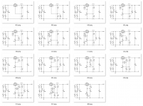
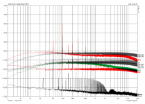
I've attached an overview of the tested circuits and the noise results here. To sum up, I'd say that "no TL431 is best", at least noise-wise. A simple Zener is at least as good, partially even better, while a simple cap outperforms both of them. Regarding the load step response, it is better to put a cap between TL431 cathode and TL431 ref instead of between LM317 out and TL431 ref.
. I simply had to hook up an LM and do some real-world measurements.Please have a look at the results here: LM317 regulator under test
I've attached an overview of the tested circuits and the noise results here. To sum up, I'd say that "no TL431 is best", at least noise-wise. A simple Zener is at least as good, partially even better, while a simple cap outperforms both of them. Regarding the load step response, it is better to put a cap between TL431 cathode and TL431 ref instead of between LM317 out and TL431 ref.
Attachments
Here you are, hope it was soon enough .
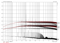
I found a BF245C on the attic (which yields about 13.5 milliamps [measured]) and quickly did the measurements while I was still 'in the mood'...
Looks like it doesn't behave that much different than a simple resisor, though. But you should look at #302 and add a cap to your units, as it helps a lot with noise but doesn't impair transient response (it actually looks even better than before).
.I found a BF245C on the attic (which yields about 13.5 milliamps [measured]) and quickly did the measurements while I was still 'in the mood'...
Looks like it doesn't behave that much different than a simple resisor, though. But you should look at #302 and add a cap to your units, as it helps a lot with noise but doesn't impair transient response (it actually looks even better than before).
Attachments
SGK, you're welcome .
The traces in red are the ones (in the second diagram I posted here), but please have a look at http://preamp.org/diyaudio/lm317-regulator-under-test, there you'll find more detailed information, like step response and actual recorded flac's for your personal enjoyment.
Pergo, any idea how I could do this? I don't own a signal generator, so what about using the soundcard as generator with an amp for the muscles and a big C to couple it in? What about the levels? And then there'll be no MHz's of course...
.The traces in red are the ones (in the second diagram I posted here), but please have a look at http://preamp.org/diyaudio/lm317-regulator-under-test, there you'll find more detailed information, like step response and actual recorded flac's for your personal enjoyment.
Pergo, any idea how I could do this? I don't own a signal generator, so what about using the soundcard as generator with an amp for the muscles and a big C to couple it in? What about the levels? And then there'll be no MHz's of course...
You can use a DC coupled power amplifier.
So at amplifier's output you can have a constant DC + AC signal.
But you need a signal generator with offset regulation to have fine tuning of output.
I don't know another way to measure such high PSRR.
High PSRR = high AC swing at input or you will not see anything over noise at output.
So at amplifier's output you can have a constant DC + AC signal.
But you need a signal generator with offset regulation to have fine tuning of output.
I don't know another way to measure such high PSRR.
High PSRR = high AC swing at input or you will not see anything over noise at output.
- Status
- This old topic is closed. If you want to reopen this topic, contact a moderator using the "Report Post" button.
- Home
- Amplifiers
- Power Supplies
- LM317+TL431, really?