It looks like if you need really low frequency rejection and can live with slightly higher noise, then the 400 Zener version should be superior to the standard 002 resistor and cap solution.
The low frequency rejection of the 400 Zener version is absolute terrific.
Thanks for the measurements, great work.
EDIT : But I still think you should try the Exar SPX2431AM, TL431 equivalent. It is so far the lowest noise TL431 or equivalent that I have been able to find(going by datasheet values).
Last edited:
1- can you lower the compensation cap in TL431 version? I use 470p for rock solid stability but my version is stable even without any compensation.
C3 in #302? I could offer you 1nF...
2- can you try step response into something between 1A and 1.5A?
Not for all the circuits and not this weekend, but I'll see what I can do.
EDIT : But I still think you should try the Exar SPX2431AM, TL431 equivalent. It is so far the lowest noise TL431 or equivalent that I have been able to find(going by datasheet values).
Pass me one and I'll try it. You'll get it back afterwards
.EUR 0,55 is not that expensive, but EUR 20,- for shipping is
. Do you know any source other than mouser?Pass me one and I'll try it. You'll get it back afterwards
EUR 0,55 is not that expensive, but EUR 20,- for shipping is
Sure, if I had one, but I don't.
I do not know of another source either, sorry.
Maybe their confirmation email sender is not at work anymore, I can't get the registration done . No samples today.
If this is what you meant, pergo: It's performing almost exactly like #100, except for the noise going down from a couple kHz onwards, being about 5dB lower than #100 at 20kHz. Nothing to rave about. Now I totally want to try that SPX...
. No samples today.C3 in #302? I could offer you 1nF...
If this is what you meant, pergo: It's performing almost exactly like #100, except for the noise going down from a couple kHz onwards, being about 5dB lower than #100 at 20kHz. Nothing to rave about
. Now I totally want to try that SPX...Lasse
I can send you one. I am based in London.
Some dumb questions: DUT = device under test? I'm, trying ti understand the rest of your test rig. The switch is used to step the load? What's the purpose of the series capacitor and diodes?
Regards
Steve
BTW I ordered some PCBs based on the circuit I posted earlier. Awaiting delivery. There will be some spares if anyone is interested.
I can send you one. I am based in London.
That's great. I'll send you my address via PM.
DUT = device under test?
Correct.
The switch is used to step the load?
Correct.
What's the purpose of the series capacitor and diodes?
AC-Coupling of the noise voltage to the soundcard. 15V would kill it...
The diodes are supposed to limit spikes to reasonable levels so they don't kill the soundcard.
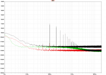
I just received the Sipex 431 from SGK and promptly did the measurements. The final diagrams have to wait till the evening, but here's a teaser (or spoiler
#302 from the previous run in black
#302 with the Sipex in red
#400 in green
Nice, just as expected, a lot better than the standard TL431.
Hmmm….
I stuffed my little regulator board today and I have a problem. Instead of reading 5V I am getting 2.45V. I am puzzled as to what I have done wrong.
I'm pretty sure I have the pin assignments for the SPX431 correct. The data sheet has a bottom view of the TO-92 package. I read this to place the cathode at the top when oriented as per the above (with the ref pin at the bottom). If I have this orientation wrong then I would expect the output voltage to be about 10V and change.
Any ideas?
PS: I have 2V at (what I believe to be) the ref of the SPX431 and only 1.2V at the adj pin of the LM317.
I stuffed my little regulator board today and I have a problem. Instead of reading 5V I am getting 2.45V. I am puzzled as to what I have done wrong.
An externally hosted image should be here but it was not working when we last tested it.
I'm pretty sure I have the pin assignments for the SPX431 correct. The data sheet has a bottom view of the TO-92 package. I read this to place the cathode at the top when oriented as per the above (with the ref pin at the bottom). If I have this orientation wrong then I would expect the output voltage to be about 10V and change.
Any ideas?
PS: I have 2V at (what I believe to be) the ref of the SPX431 and only 1.2V at the adj pin of the LM317.
Last edited:
That's it, the graphics are online. For your convenience again:
click here
Yeah, the SPX is actually a lot better than the ET, but not with Mark's circuit (#320). There's some strange low-frequency rumble there which doesn't look nice in the time domain; step response is also impaired.
Now that was quite a bit of work, more than I had imagined. Gotta find a bulky 10 to 15 ohm resistor for pergo's load test now...
I'm planning to test a 7815 for comparison, too, and if I'm really bored over the next weeks I might even examine the benefits of a capacitance multiplier downstream. Maybe even a noise shunt. Getting complicated now, circuit-wise
I stuffed my little regulator board today and I have a problem. Instead of reading 5V I am getting 2.45V. I am puzzled as to what I have done wrong.
Pinout is correct. Looks like the Anode is floating, though.
EDIT: ... just noticed that the whole ground layer is not shown, but I suppose it's actually there
Did you try to short out R1? Or replace the CCS with a simple resistor (use 243 in this case)?
Everything seems to be correct, be sure to check for soldering errors or even faulty tracks (shorts to the ground layer [don't know your clearance] or discontinuations).
EDIT: NOW! Gate and R1 are supposed to be connected to the Cathode of the 431, not Ref like you did!
Everything seems to be correct, be sure to check for soldering errors or even faulty tracks (shorts to the ground layer [don't know your clearance] or discontinuations).
EDIT: NOW! Gate and R1 are supposed to be connected to the Cathode of the 431, not Ref like you did!
Last edited:

To go single layer I would have to route the C1 to the input of the LM317 all the way around the board plus rearrange things to deal with R1 to source. Is it such an issue? (I thought the via would be covered by solder mask but it isn't.) The tracks are 1.6764mm. Not enough?
Hopefully this is better:
I haven't done the ground planes or silk screen yet.
(this is becoming the most expensive little DC regulator ever built…I'm certainly learning to pay more attention to detail)
An externally hosted image should be here but it was not working when we last tested it.
I haven't done the ground planes or silk screen yet.
(this is becoming the most expensive little DC regulator ever built…I'm certainly learning to pay more attention to detail)
- Status
- This old topic is closed. If you want to reopen this topic, contact a moderator using the "Report Post" button.
- Home
- Amplifiers
- Power Supplies
- LM317+TL431, really?