millwood said:I am starting to think that some kind of choke in place of the upper source resistor may be the way to go in order to kill the turn-on rush current. Any thoughts?
I not convinced that chokes are the most elegant solution for the inrush problem. It is though an interesting possibility.
It means you can half the PSU voltage for the same o/p.
The question is: how good does the choke have to be to avoid it compromising the HF and/or LF response and distortion.
to avoid LF compromise there would need to be an air gap in the core otherwise the dc standing current will saturate the core.
to avoid HF compromise the choke would need to have a high resonant frequency this may mean special winding techniques.
of course it would be fun just to try it using the secondary of a largish transformer.
be careful to insulate the primary because there would be very high voltages induced in it.
mike
Hi Millwood,
I think I solved my startup current rush problem..
I first did somesimulation: grounding the input, and using a signal generator (square wave f=0.1Hz @ 30Volt) as a power supply.. This indicated a 7A inrush current, while allmost all voltage goes over the upper transistor... I think this is due to my input arangement :
15K -> 470uF to ground -> 100K -> input -> 100K
The 470uF is to filter away the 100Hz residual rectifier rimple.. I changed it to 4.7uF and now everything works nice..
Your problem might be different. You could also try a capacitor multiplier/with current limmitor and refernece voltage for a nice regulated supply.. but that would be just asmust work as a whole amplifier...
Goodluck,
Thijs
PS
I building my second MOSFET channel now, asing BD139 as driver. .. can't wait to compare the BJT and MOSFET....I'll post my schematic and what I think is an near optimum MOSFET JLH schematic... I have found something new...")
I think I solved my startup current rush problem..
I first did somesimulation: grounding the input, and using a signal generator (square wave f=0.1Hz @ 30Volt) as a power supply.. This indicated a 7A inrush current, while allmost all voltage goes over the upper transistor... I think this is due to my input arangement :
15K -> 470uF to ground -> 100K -> input -> 100K
The 470uF is to filter away the 100Hz residual rectifier rimple.. I changed it to 4.7uF and now everything works nice..
Your problem might be different. You could also try a capacitor multiplier/with current limmitor and refernece voltage for a nice regulated supply.. but that would be just asmust work as a whole amplifier...
Goodluck,
Thijs
PS
I building my second MOSFET channel now, asing BD139 as driver. .. can't wait to compare the BJT and MOSFET....I'll post my schematic and what I think is an near optimum MOSFET JLH schematic... I have found something new...
mikelm said:I not convinced that chokes are the most elegant solution for the inrush problem. It is though an interesting possibility.
mike
I would agree. My hypothesis for the turn-on rush current is that it is caused by that input filter cap that temporarily tied the base of the input transistor to the ground thus dropping 1/2 rail voltage on the GS junction of the upper mosfet. tschrama cured the rush current problem by reducing the 470u in my design to a much small figure.
I am couries as to if the turn-on rush current thing is also existent in the BJT version. My analysis is that it should but to a less extent.
tschrama said:Hi Millwood,
I think I solved my startup current rush problem..
The 470uF is to filter away the 100Hz residual rectifier rimple.. I changed it to 4.7uF and now everything works nice..
thanks. I will have to find a small cap somewhere and try it out.
BTW, I think I have turned my turn-on thump by using a 0.47ohm source resistor vs. 0.2ohm originally. It doesn't have much impact on turn-on rush current though.
tschrama said:PS
I building my second MOSFET channel now, asing BD139 as driver. .. can't wait to compare the BJT and MOSFET....I'll post my schematic and what I think is an near optimum MOSFET JLH schematic... I have found something new...
what happened to your idea of using the irf for driver? that would be an interesting experiment,
Looking forward to your report.
another possible modification is to turn the output into a fully complementry BJT or MOSFET stage.
as someone had pointed out, the driver stage isn't symmetric as the Zout differs substantially. The same goes for the all NPN/N-channel output stage: the upper one is a common emiter and the lower one common collector. What if we use a fully coomplementry stage to turn this all into common emitter stage?
i would go with a mosfet version as they wouldn't overload the driver stage.
Any thoughts?
You're going too fast Millwood ... I acually have the same thoughts and experimented with them this weekend.
I solved the a-symmetrically output impedance of the driver by using drifferent gate-snooper resistors: 150Ohm / 820Ohm using 470 driver resistors.
The effect is visible on my scope and simulations (again they agree ) , but only at very high frequencies.. I optimized the 100KHz square wave using these values... Now the upper and lower MOSFET are sharing AC current equally even at HF...
I also simulated a complementair Class A MOSFET version.. It looks very much like JLH 15W Class AB amp. but without the driver-buffer... If you haven't read that article allready I can recommend it highly. It's on the 'Class A website'.
It nice to see that the MOSFET complenmentair version achieves very similar specs, with about the same parts count... slightly better at HF.
My first channel is a BD139 so I thought that my second channel should be alike.. Besides... I don't need the extra bandwidht (> 1MHz!) .. I am more concerned about overshoot, than about bandwidth...as this could be the cause ofmy earlier MOSFET failures during 1MHz aquare wave tests..
Turn-on-bump: my BJT has it too, but I can't remember the capacitor value... but it is not bad. My MOSFET version now only has a very slight 'blop'... I can't really test for rimple rejection, since I use a regulated supply.. but I think most humm problems are bad grounding layout .. I don't think the MOSFET version has inherently better rimple rejection, but I could be wrong.. again...
Best regards,
Thijs
PS
... I acually have the same thoughts and experimented with them this weekend.I solved the a-symmetrically output impedance of the driver by using drifferent gate-snooper resistors: 150Ohm / 820Ohm using 470 driver resistors.
The effect is visible on my scope and simulations (again they agree
) , but only at very high frequencies.. I optimized the 100KHz square wave using these values... Now the upper and lower MOSFET are sharing AC current equally even at HF...I also simulated a complementair Class A MOSFET version.. It looks very much like JLH 15W Class AB amp. but without the driver-buffer... If you haven't read that article allready I can recommend it highly. It's on the 'Class A website'.
It nice to see that the MOSFET complenmentair version achieves very similar specs, with about the same parts count... slightly better at HF.
My first channel is a BD139 so I thought that my second channel should be alike.. Besides... I don't need the extra bandwidht (> 1MHz!) .. I am more concerned about overshoot, than about bandwidth...as this could be the cause ofmy earlier MOSFET failures during 1MHz aquare wave tests..
Turn-on-bump: my BJT has it too, but I can't remember the capacitor value... but it is not bad. My MOSFET version now only has a very slight 'blop'... I can't really test for rimple rejection, since I use a regulated supply.. but I think most humm problems are bad grounding layout .. I don't think the MOSFET version has inherently better rimple rejection, but I could be wrong.. again
...Best regards,
Thijs
PS
Could you draw what you mean?What if we use a fully coomplementry stage to turn this all into common emitter stage?

millwood said:another possible modification is to turn the output into a fully complementry BJT or MOSFET stage.
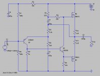
I haven't been able to get it to work. But here it goes.
Conceptually, I wanted to take advantage of the phase splitter: using the voltage drop off C and E of it to drive a pair of mosfets.
But my trouble is that I couldn't get anough voltage for the negative half of the signal,
. Will think about it more over the holidays.Alternatively, I can also get a small resistor in C of the driver, as JLH did with his class AB amplifier.
Attachments
Hi Caleby,
I guess I better let you know why I said 'Yeuchhhh !'
When I saw that long strip of copper between Q1-C and Q2-E, and its proximity to the input transistor, I immediately thought 'fields'.
The JLH-69 circuit itself has an amplifier bandwidth that extends into radio frequencies, even when its input is filtered.
I would have had more input to ouput separation to minimise capacitive coupling, also wire as I previously explained so as to not risk magnetic coupling by having a through-pcb track like that.
The most significant weakness of the JHL circuit is the lack of turn-off for the lower output device; this is the reason for its slower (but unimportant) positive slewing capabilities on square-waves. This is the main cause of cross-conduction spiking through the output devices on sibilants and percussive crescendos. These spiking currents can momentarily upset biasing, with an increased risk of ringing recovery.
I note that you use the later JLH input filter, which maybe produces a more valve like characteristic. However, I prefer the sonic definition of adulterated phase linearity as with the original version with a larger output 'C'.
I might have said that this is not the best amplifier possible, meaning as far as THD specifications are concerned, but in modified form it remains my amplifier of choice. I have yet to find another amplifier that comes close. Many supposedly 'ultimate' solid state designs with THD lower than 0.01% just don't cut it when it comes to driven loudspeaker cone control; also while valve designs can be good, and generate *less* heat for the same power, they are limited by their extremely costly output transformers.
At least your input capacitor at the base of the first transistor is going to reduce any capacitive coupling that might arise between input and output circuitry.
Cheers ........... Graham.
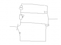
In such a complementair buffer output stage.. I think you need to drive the MOSFETs in phase.. not anti-phase?
like this:
attachement
Regards,
Thijs
PS just got back from electronics shop for 4 1 Ohm resistors.. I got me a rectifier along the way for a unregulated supply... I'll be back...
like this:
attachement
Regards,
Thijs
PS just got back from electronics shop for 4 1 Ohm resistors.. I got me a rectifier along the way for a unregulated supply... I'll be back...
Attachments
Hi Graham, welcome to the DIYaudio forum... your comments are appriciated... in particulary this one:
since I tend to agree with this one .. Using the emmitor/source resistors, you can see the cross cunduction happening on a scope.. so far the BJT seems to suffer fromthis effect more than my MOSFET version.. Talking about MOSFET version
  I suggest you go over the thread again and simulate/build one .. you might get supprissed
Best regards,
Thijs
The most significant weakness of the JHL circuit is the lack of turn-off for the lower output device; this is the reason for its slower (but unimportant) positive slewing capabilities on square-waves. This is the main cause of cross-conduction spiking through the output devices on sibilants and percussive crescendos. These spiking currents can momentarily upset biasing, with an increased risk of ringing recovery.
since I tend to agree with this one
.. Using the emmitor/source resistors, you can see the cross cunduction happening on a scope.. so far the BJT seems to suffer fromthis effect more than my MOSFET version.. Talking about MOSFET version I suggest you go over the thread again and simulate/build one .. you might get supprissed Best regards,
Thijs
tschrama said:you might get supprissed
the single biggest shortcoming of the mosfet, in my view, is the turn-on rush current. Unfortunately I don't have a BJT version to compare to.
the fortunate thing is the mosfets are a lot more rugged than the BJTs,
.I am now very intrigued about the complementory configuration.
millwood wrote:
I don't know if it already has been suggested, but have you tried thermistors at the mains side in order to reduce inrush current? Nelson Pass usually recommends CL60, Digikey # KC006L-ND.
/Niclas
the single biggest shortcoming of the mosfet, in my view, is the turn-on rush current. Unfortunately I don't have a BJT version to compare to.
I don't know if it already has been suggested, but have you tried thermistors at the mains side in order to reduce inrush current? Nelson Pass usually recommends CL60, Digikey # KC006L-ND.
/Niclas
Calebay said:Hello
Graham, so your saying it will be better for me to use a smal PCB lets say 60 x 80mm in the midle of my mone block and then use wire out to q1 and q2. is it good or baad to twist this wires to EBC.

Calebay: one thing I have learnt about the mosfets is that if you use wires to connect them to PCBs, you run a huge risk of parasitic oscillation. I always mount mine on PCB, with the shortest path possible.
stappvargen said:I don't know if it already has been suggested, but have you tried thermistors at the mains side in order to reduce inrush current? Nelson Pass usually recommends CL60, Digikey # KC006L-ND.
/Niclas
Niclas, I am not sure if we are talking abou the same inrush current. Yours is probably PS / filter cap related. Mine relates to the sudden turn-on of the upper output device in the JLH1969 design.
I was just looking at the SOA for 2n3055. At 30v, maximum Ic is about 4amp DC, and 7amp 1ms. I suppose the bjt version's inrush current is nowhere near those figures. so indirectly it verifies that the BJT performs better in the turn-on rush current department.
the mosfet version would be harder to parrallel, given the very high turn-on rush current. However since the irf540s can withstand upwards of 100amp of peak current, it should have no impact on the devices themselves.
millwood wrote:
I admitt to not having understood the difference of the two problems. My thinking was that by limiting the current to the amp at turn-on you would in effect limit the current to the upper output device. How can you get a current surge if you have no power?
/Niclas
Niclas, I am not sure if we are talking abou the same inrush current. Yours is probably PS / filter cap related. Mine relates to the sudden turn-on of the upper output device in the JLH1969 design.
I admitt to not having understood the difference of the two problems. My thinking was that by limiting the current to the amp at turn-on you would in effect limit the current to the upper output device. How can you get a current surge if you have no power?
/Niclas
stappvargen said:My thinking was that by limiting the current to the amp at turn-on you would in effect limit the current to the upper output device. How can you get a current surge if you have no power?
/Niclas
Sorry. I see your point now. Maybe it is even better to use that on the positive rail.
- Home
- Amplifiers
- Solid State
- JLH 10 Watt class A amplifier