tschrama said:I *think* I can hear a difference in sound quality as I reduce idle current below 800mA (2 channels).
Greetings,
Thijs
I can definitely hear sound difference at 750ma: it is a little "coarse" and broken, not as smooth, especially on the highs. I suspect 1amp is a little low, and I would prefer 1.3 - 1.5amp but it does get a little hot (warm to hot) on my P2 heatsink at that bias level.
Graham Maynard said:Can I add that distortion is lower again when the bootstrapped collector resistor and the emitter resistor at the current splitter are also equal, as Tschrama has done with his 470Rs.
it makes sense that the A/C voltage variation on the upper mosfet gate is the same as the that on the lower mosfet gate: assuming both are equal in gains.
But how does that translate into equal value for the emitter resistor and lower resistor of the bootstrap? While we are at it, what is the "A/C equivalent" resistance of the bootstrap? how doe sthat tie to the value of both upper and lower bootstrap resistors?
tschrama said:
1]both the driver-resistors must be of equal value, and
2]both MOSFETs must has equal transductance ( 0.5R source resistance helpt but not really nessecery)...
3]The 'not-realy-a-bootstrap' capacitor must act as voltage source, so it impedance must be << 766R at all frequencies..
I am quiete convinced that I'm not mistaken, I've simulated it, build it, and measured it, this is how it works..It even sounds good
Best regards,
Thijs
Tschrama, you are quite correct with the analisys above. However the point 3 is not as simple as you may think. Just look at the symmetry at the low frequency end - you'll see it raise considerably even with a reasonably large bootstrap capacitor as in your diagram. So the amp will have a hint of SE-ness in the bass
Cheers
x-pro
millwood said:One way to think about this is to assume very high gain BJT devices in the BJT version, and it will then become a "voltage" driven output stage->aka the mosfet version.
it was interesting to note that jlh in his original 1969 article also mentioned that the use of "high gain' bjts was recommended.
Had he had some irf540s in his possession then, we might have never known the BJT version,
Hi all,
X-pro, all your comments are right on the spot. I troubles me a bit. So what should we do? Your design doesn't suffer from that problem, am I right?
Indeed , if he was still a active designer this day (i s he? ), maybe he would publish an update using MOSFETs, higher and symmetrical Vsupply.
G'night,
Thijs
X-pro, all your comments are right on the spot. I troubles me a bit. So what should we do? Your design doesn't suffer from that problem, am I right?
Had he had some irf540s in his possession then, we might have never known the BJT version,
Indeed , if he was still a active designer this day (i s he? ), maybe he would publish an update using MOSFETs, higher and symmetrical Vsupply.
G'night,
Thijs
Just look at the symmetry at the low frequency end - you'll see it raise considerably even with a reasonably large bootstrap capacitor as in your diagram. So the amp will have a hint of SE-ness in the bass .
One way to measure it mioght be to disconnect the speaker as feed the amp with some low-frequency signal. Since there is no load connected to the outut, no significant current will flow through the source resistors of the MOSFETs. But is the phase-relationship is lost (due to phase-shift in the 'not-a-real-bootstrap-anymore' ) significant cross-conduction should accur...well in mine it does... so indeed we have a partially SE amp
gr,
Thijs
tschrama said:Hi all,
X-pro, all your comments are right on the spot. I troubles me a bit. So what should we do? Your design doesn't suffer from that problem, am I right?
Thijs
Yes, as my design uses a current source to set the idle current, it is not affected much by the power supply variations. Indeed in the last revision of Creek Audio 5350SE integrated I did manage to maintain the idle current over supply and temperature (from 20 upto 80 C on the heatsink) variations down to less than 10% from 65 mA without any source resistors in the circuit. I've calculated that it indicates about 0.1% precision of tracking the Vgs of the output devices. I'm actually fairly proud of that circuit
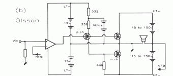
Strictly speaking you may try to use a current source instead of the top resistor in your circuit - it may even work better. Your circuit actually looks a bit like the design by Olsson published in EW+WW Dec 1994 - I attach the scan here (from Ben Dunkan's book "High Performance Audio Power Amplifiers" - an excellent book on the subject). As you may see Olsson used a "battery" (actually a zener-like network) instead of a bootstrap capacitor.
I can also add that my circuit actually predates Olsson's publication by more than two years.
Cheers
x-pro
Attachments
JLH PSU Caps
Hi all
Sorry Chaps but can we not keep this thread two the JLH Class a Amp I had shelf this amp due to being out of work for some time but its back on the bench 15 watt version I Have most of the Parts for the amp now But the cost of the PSU Supply Caps Are a bit top [end for the audiophile split foil types Can you chaps recommend a good starting value for this amp with a view to add caps as funds permit
Thaks All
Colin
Geoff said:Extensive simulation over several years using a variety of output transistor models has indicated to me that the peak output current from a JLH Class-A will be between 1.3 and 1.6 times the quiescent current, depending on the output devices used.
Geoff
there is no magic in the 1.3-1.6 figure.
a class a should swing the full output in its linear range. Take my amp for example. It has a gain of 10x, the same with the original jlh design. so a 1vp signal will generate 10vp on the output, or a 20vp swing. On an 8-ohm nominal load, that's 20/8=2.5amp. Assuming that the linear range for the transistors start at 0, the Iq should be set at the middle of the output range, or 1.25amp.
However, very rarely a transistor starts out to be linear to you may want to overbias a little. that means the bias should be slightly over 1.25amp. My listening test shows that bias between 1.2 - 1.5amp tends to be optimal, or 1x - 1.3x of peak current output (10v/8ohm).
if we are using perfect transistors, the ratio should be exactly 1x.
tschrama said:The 4.7uF input bias cap is choosen to speed up the turn-on-bump (now only a few ms).
the turn-on thump may be more complicated than we thought.
I don't have a small cap for the input cap. so I decided to short the 10K resistor feeding into the cap from the rail (I think you used a 39K resistor for that, as JLH used in his original design). That effectively reduced the time constant for the RC network down to zero, similar to what one would have gotten with an ultrasmall cap.
The amp broke into low frequency oscillation (like one turn every 2 - 5 seconds), and that got carried onto the sound.
In the meantime, I am staying with a large cap there. I guess I will have to use beefier PSU and thermistors to deal with the turn-on thump.
POST 696.
Thanks for the suggestion Tschrama. I've now saved the last four pages of this forum to my Desktop, so I can look back and reply without needing to change Internet Explorer.
POST 697.
Hi Millwood,
Because I was new here I was trying to stay out of the argument relating to gain matching and class-A; it is easy to become distracted by, and then defend technical minutii whilst losing sight of the bigger picture.
However, you have questioned fundamental class-A push-pull operation, and enquired about references.
You are registered in the US, so can I suggest that any 70-odd year old edition of the McGraw-Hill published 'Radio Engineers Handbook', under, "Push-Pull Power Amplifiers: Class-A, AB, and B." covers class-A fundamentals.
Here you will find the classic graphical load-line illustration of how a class-A triode push-pull response becomes linearised, and how the even harmonic distortion that arises due to the curved transfer characteristics of the individual devices separately operting together, actually cancel out in class-A push-pull.
If the characteristics are different there cannot be the same degree of error cancellation, and it is easy to see that if the curves of one push-pull half are compressed due to a lower conductance (gain) characteristic, that their push-pull distortion will be worse than when a matched pair of low gain devices are used; which was all they had in the 20's and 30's !
Bipolar amplifier transfer characteristics are curved similar to triodes, though through most of their useful working range, modern high spec and gain tailored Mosfets are not. If you were thinking and reasoning about, and therefore applying, the highly linear transfer characteristics of modern Mosfets to your argument, then your original statements cannot be criticised;
but bipolars ?
Also I must advise you that, when overdriven, the JLH-69 will *not* run into class-AB.
This is why Mr Lindsey-Hood developed a second slightly more powerful class-AB version.
His class-A topology has a fixed output stage bias current supply that is shared between the output devices; there is nothing extra for overdriving.
The JLH-69 just clips cleanly and quietly with a slight shift in the zero bias potential as first one half conducts to maximum and its partner goes off, and then vice-versa.
With extreme and decidedly non-audio overload, the bias will shift even more as input transistor currents flow through the driver's base-emitter junction and directly into the lower output device, causing a shift in the bootstrap voltage. And yet all this happens without waveform spiking; also there is no risk to the output devices.
POST 709.
Hi Colin.
Just use what you can to start with, and leave space and access for improvements. I'm sure you wouldn't mind a very slight hum by getting started with a simple bridge and 10,000uF. Don't waste funds by using audiophile quality capacitors in the psu.
'FarnellInOne' sell some good Panasonic capcitors by credit card and telephone order, also with a free first class post delivery and no minimum. They can be found on the 'net, but their capacitor finder is atrocious.
Happy Christmas everyone................ Graham.
Graham Maynard said:If the characteristics are different there cannot be the same degree of error cancellation, and it is easy to see that if the curves of one push-pull half are compressed due to a lower conductance (gain) characteristic, that their push-pull distortion will be worse than when a matched pair of low gain devices are used;
there is no question about that. But "characteristics" mean a lot more than gain matching. And in this particular "academic" exercise, the "gain" was more or less referred as one number, not a curve or a set of curves.
In otherword, if we had a transistor whose "characteristics is represented by one figure under all condition, will we still get worse distortion performance if the "characteristics" of two output devices aren't matched?
I venture to say "no".
BTW, does the push-pull analysis in your reference use all npn or all pnp devices?
Graham Maynard said:Also I must advise you that, when overdriven, the JLH-69 will *not* run into class-AB.
His class-A topology has a fixed output stage bias current supply that is shared between the output devices; there is nothing extra for overdriving.
First of all, the bias for the output stage in the JLH1969 is NOT constant. Had JLH used two perfect current sources as the collector and emitter load for the driver, or one perfect curent source as the collector load and eliminate the emitter resistor for the driver, as Geoff had suggested, I would agree with you. The matter of fact, unfortunately, is that he used two resistors (well, one bootstrap network + one resistor) in his design.
Again, going back to the assertion that the MOSFET version isn't a push-pull, I am of the view that it is completely wrong. I am also of the view that the orginal jlh design is better suited for voltage driven output devices like mosfets.
I thought about this class ab thing a little bit more.
let's make an assumption: the Iq on the driver stage is significant larger than the base current for the two drivers: in my mosfet version, the iq for the driver is 40ma.
Now, as the driver's collector current goes down (on positive side of the signal), voltage drop off the bootstrap network goes down, forcing the upper output device to conduct more, to the point where the voltage drop off the emitter resistor of the driver goes below 0.7v, shutting off the lower output device.
If the signal continues to go positive, the lower output device will remain off but the upper one will continue to open up -> the amp is in class AB mode for the positive side of the signal.
The reverse is also true but a lot trickier. As the collector current goes up (on the negtive side of the signal), voltage drop off the bootstrap will go up, shutting down the top output device.
As the signal continues to go negtive, the top device will remain closed. The lower output device will not be able to remain open (actually it can, due to the stored charges in the output capacitor but that's another story). so the amp cannot swing as much in the negtive cycle as it does in a positive cycle.
When I drove the jlh1969 with a 2vp signal, what I saw is a somewhat sine wave on the positive side but chopped off bottom on the negtive side, consistent with the above analysis.
the limitation on the negative swing will be eliminated in a due-rail configuration (the updated jlh for example).
In short, the orginal jlh can swing into class ab on the positive side but not able to do so on the negtive side. I believe the mosfet version faces the same limitation (more so I think because the mosfet version isn't as efficient).
- Home
- Amplifiers
- Solid State
- JLH 10 Watt class A amplifier
 .
.