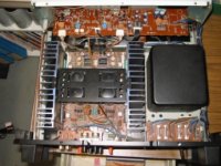
JLH in Technics SE-A5 enclosure
I'm thinking I'd like to put my upcoming JLH in this old amp case. I can use the inner windings on the transformer (24-0-24) and a cap multiplier / regulator circuit to bring down the voltage to a reasonable level. I may be able to fit some fans in above the heatsinks to cool off all the transistors (cap mult. & parallelled outputs, 12 transistors I think).
The single supply idea may also work, but as I don't have two independent secondary windings I'd have to use a full-wave CT arrangement.
Thanks for Geoff for providing me with a single-supply version of the latest JLH design some time ago. I have a prototype single channel but haven't got any further as yet.
Any thoughts?
Attachments
thermal stability
I have been taking a timed test of the current going through the upper source resistor for sometime. here is the result.
first of all, I am idling my mosfet jlh at about 1.2-1.3amp (250mv on 0.2ohm resistor). during the first 20-25 seconds, there is a huge current going through the amp. the voltage on the 0.2ohm resistor goes from 1v down gradually to 0.25v. It then kind of drifts between 0.25v - 0.26v.
It tend to be on the high end of the voltage if no music is playing and low-end of the voltage with music playing.
the case is hot to the touch but the heatsink is warm - hot to the touch.
That looks like a nice big amplifier Paulb,
are you sure that you want to dismantle it?
A 24-0-24 trannie is suiteble for single 30V supply isn't.. for a dual supply it might be a bit high for class A.. do you have any idea what the wattage rating was for the power supply/amp?
Goodluck,
Thijs
are you sure that you want to dismantle it?
A 24-0-24 trannie is suiteble for single 30V supply isn't.. for a dual supply it might be a bit high for class A.. do you have any idea what the wattage rating was for the power supply/amp?
Goodluck,
Thijs
Hi Millwood,
I got my amp up and running again. I have found a good way to damp the ringing without slowing the amp down. It is actually a fast amp going 20/-30V/us slewrate. It now measyres better than my BJT version. ... I think I want to build the second chammel with a IRF510 as driver, since it can handelmore current than the BD139, I can scale the driver resistor down to 100 Ohm, making the amp still faster...
I also have a big startup current which takes quiete long to fall back a gain. I still think it is something with the bootstrap or input bias capacitor, but since it goes so slow, it might as well be the termal effect on the Vgs@ threshold.. oris this not possible...hmmm datasheet.....?
I was wondering if you have done a long term Iq measurement too? Mine is not stable, 3% ppower supply increasemake my Iq go from 600mA to 900mA....
best regards,
Thijs
tschrama said:I was wondering if you have done a long term Iq measurement too? Mine is not stable, 3% ppower supply increasemake my Iq go from 600mA to 900mA....
best regards,
Thijs
Thijs: I measured my Iq (actually voltage drop over the upper source resistor) for over 5 - 6 hours. It is rocksolid at about 250-260mv (or 1.25a-1.3a). Unfortunately, i don't have a regulated power supply so I cannot test the Iq-Vc relationship.
However, your observation (that Vc has a huge impact on Iq) makes a lot of sense. the (DC) voltage drop off the bootstrap resistors are pretty much the same regardless of Vc (it is determined by Ic of the driver which in turn is determined by Vgs of the lower mosfet plus the emitter resistor on the driver). so any rail volgate increase will increase Vgs by 50% thus Iq will increase. if you look at the IRF datasheet, a 0.5v increase in Vgs (from 4v - 4.5v) will increase Iq from 1a to 6a.
the source resistors will provide some negative feedback so that seems to suggest to use as high of a source resistor as you can, without sacrificing efficiency and power.
tschrama said:I have found a good way to damp the ringing without slowing the amp down.
what's it?
tschrama said:I think I want to build the second chammel with a IRF510 as driver, since it can handelmore current than the BD139, I can scale the driver resistor down to 100 Ohm, making the amp still faster...
yeah. what I learnt in my simulations is that the higher the current on the driver, the fewer problems you will have,
")
but you should be fine with bd139. the soa at 30v is about 200ma. even if you derate it a little it is still pretty healthy.
On the other hand, using the mosfet as driver may help out the input transistor a lot.
please let us know how it goes.
this is my first class a and am quite surprised how simple it is and how easy it is to put together.
tschrama,
I just checked irf510's datasheet. the remarkable thing about it is that the ciss is very low (180pf, vs. like 1800pf for irf540). so it may be a good candidate for the driver as it will not overload the input transistor as the irf540 would had you used it).
John Curl mentioned in another thread about some small signal mosfet transistors. it may be interesting to go all the way, build a all mosfet jlh, starting with small signal mosfet as input, irf510 (another candidate would be irf630) as driver and irfp240 as output. Increase the rail voltage to somelike 50 - 60v and see what we get.
how does that sound?
 OK.. I've had it with this IRF540 ... this is the third one that I've managedto blow... NOTE.. I've never effer blown a BJT.. now 3MOSFET in 2days.....
 It happend during turn on.. a current russ of about 3.5 A.. and then nothing.. the lab-supply indicating a deadshort......grrrrr
Yes, it's broken and I guess I could repair it but I have more fun building than fixing.tschrama said:That looks like a nice big amplifier Paulb,
are you sure that you want to dismantle it?
A 24-0-24 trannie is suiteble for single 30V supply isn't.. for a dual supply it might be a bit high for class A.. do you have any idea what the wattage rating was for the power supply/amp?
Goodluck,
Thijs
Lemme get my notes...it's rated for 160W into 4 ohms, but it has inner 24V taps on the secondary winding. For some reason, they have a low/high power switch that selects between the two transformer voltages. I figure that will give me lots of current so the transformer should be okay.
The voltage is a bit high, which just means extra dissipation in the regulator transistors. I'm planning on tweaking voltage and bias current to even the dissipation among transistors and to set whatever I can get away with before the temperature gets too high.
Odd to get about 10W per channel from a 320W amp...
I looks like you will be OK with your transformer.. (those heatsink look nice too...) ..
My Technics has a similar feature, a switch to chosse between 4 and 8Ohm, selecting different volatge taps on the power transformer.. I think that is neat...
I don't know what your plans are, but counting 12 power transistor could mean you are going for a ESL-version, with double bias current?
Well .. I sure you're going to buyild something good... keep us posted
Gr,
Thijs
My most recent modifications:
To limit start-up current I changed the 470uF input bias capacitor to 4.7uF.. the 470uF was really stupide giving 0.02Hz f-3dB.. wayyyyy to long...... further more the bootstrap capacitor is changed from 100uF to 22uF giving a 10 Hz f-3dB ...
I don't know if this cures things since there's something of a thermalmechanismeworkingtoo I think.. It seems that the Ibias drops slowly as the MOSFETs get hot.. must be the trancductance versus temp curve ... but according to the datahseet the Vgs threshold versus temp has a negative coefficient...
Anyway, it's up and running again.. I measured the Iac across both source resistors.. they were equal.. so current sharing is near optimum...
A 220pF damping cap from driver collector to ip transitor emmitor cleaned the 100Khz square wave perfectly ...
Cya all,
Thijs
To limit start-up current I changed the 470uF input bias capacitor to 4.7uF.. the 470uF was really stupide giving 0.02Hz f-3dB.. wayyyyy to long...... further more the bootstrap capacitor is changed from 100uF to 22uF giving a 10 Hz f-3dB ...
I don't know if this cures things since there's something of a thermalmechanismeworkingtoo I think.. It seems that the Ibias drops slowly as the MOSFETs get hot.. must be the trancductance versus temp curve ... but according to the datahseet the Vgs threshold versus temp has a negative coefficient...
Anyway, it's up and running again.. I measured the Iac across both source resistors.. they were equal.. so current sharing is near optimum...
A 220pF damping cap from driver collector to ip transitor emmitor cleaned the 100Khz square wave perfectly
... Cya all,
Thijs
Output caps
Geoff!
I like the idea you gave me with the output caps!
Could you give me some more detail about your suggestion?
(uF, V ratings, place, etc, may be a schematic?)
I have some very nice Siemens Elko what I could use for out caps....
2200 uF/63V paralel with a 2-10uF MKP?
Thanks!
Geoff!
The other is to parallel the transformer secondaries and have a single 30V rail. This will require the use of an output capacitor, a device not favoured by many people. However, you would be able to set the quiescent current to 2.7A (with only single output transistors) which would give an output power of nearly 25W (50Wpeak) into 4ohm.
I like the idea you gave me with the output caps!
Could you give me some more detail about your suggestion?
(uF, V ratings, place, etc, may be a schematic?)
I have some very nice Siemens Elko what I could use for out caps....
2200 uF/63V paralel with a 2-10uF MKP?
Thanks!
Re: Output caps
I thought you wanted the updated version which runs off dual rails.
Anyway, if you want to run off just one 30v rail, you can use just full wave rectification to achieve it, no need to parrallel the 2ndary windings. This is simplier and you don't need to worry about unequal 2ndary windings.
Tyimo said:Geoff!
I like the idea you gave me with the output caps!
Could you give me some more detail about your suggestion?
(uF, V ratings, place, etc, may be a schematic?)
I have some very nice Siemens Elko what I could use for out caps....
2200 uF/63V paralel with a 2-10uF MKP?
Thanks!
I thought you wanted the updated version which runs off dual rails.
Anyway, if you want to run off just one 30v rail, you can use just full wave rectification to achieve it, no need to parrallel the 2ndary windings. This is simplier and you don't need to worry about unequal 2ndary windings.
Hi All.
I'm new here, and have just found this string. I find it very interesting, but disappointing too ..... what's with the Mosfets ?
The JLH-69 is a current controlled amplifier with near floating voltage nodes after the first transistor base emitter junction.
Mosfets rely upon voltage drive!
I built many JLH-69s after the original publication, and 30yrs ago, a triple parallel 2N3055, 50W-8R version that still survives after repeatedly showing off its ability to withstand noisy loudspeaker lead sparking under full input drive.
It had (has) current sources for the first transistor collector, as well as for the second transistor collector, and emitter. The PSU has never been below 63V, often 70V !!, and it has never failed.
POST 511.
Yes Selim. I have tried split nfb loops. There was no advantage.
Actually there is a slight increase in bass cone breathing due to the increased 'Q' effect of reactive components being enclosed by the overall nfb loop.
POST 624.
Geoff's biasing suggestion was in my 50W'er. It mostly overcomes single rail psu power-up thumping, though the loudspeaker can be seen 'drifting' for about ten seconds as bias currents settle. Can't remember my exact values. I also slugged the second transistor collector current source .
There is a need to be sure of psu supply continuity here though, because a momentary break could leave the first transistor with substantial bias at restart, whereupon the thud becomes a cone-busting crash. If Geoff's circuit is used, a pull down diode must be connected to to the +ve rail.
POST 550.
I particularly agree with X-pro's statements, but also see
POST594. for necessary qualificarions.
First transistor collector load bootstrapping ? Why bother ? You might fractionally improve the *sine-wave* distortion figure, but you also introduce an unwanted high frequency phase change which can reduce the overall stability margin. Also you are introducing to the first collector, output voltage components that vary with lower output device Vbe + Vcb + series emitter resistor potential, which do not match collector voltage at higher nfb loop controlled frequencies.
POST 629.
Also for those who are trying Mosfets, do remember that you are inserting within what once was a stable nfb loop, gate device capacitances that vary with both frequency and alternating voltage amplitude.
Additionally the second JLH transistor can reverse bias an unprotected top output device at power-up and on transients. Then if you protect the top output Mosfet, you could damage the second transistor.
There are more pitfalls than gains in trying to implement Mosfets in the JLH-69 circuit, not least being the much reduced thermal efficiency. Mosfets need some non-linear current drive as well.
POST 623.
30yrs ago I used 10mF of output capacitance because dropping back to 2m2F (2,200uF) was noticeably worse on some loudspeakers. If you have 'bouncy bass', then increase your output 'C'. 2m2F causes serious low frequency phase distortion, with a sort of out of phase nfb loop induced damping which does not arise with direct coupling.
The basic JLH is not the best amplifier circuit around, but when carefully made and run within its capabilities I don't know how anyone could not be satisfied, as long as PA performance is not wanted.
Within this string there is a pcb layout that made me go 'yeuchhhh'. It is a long narrow layout with power devices at opposite ends. I have always separated input circuitry from power plus output device connections by having them at opposite ends of a pcb. I have never needed to apply any extra stabilizing components.
If anyone is unhappy with the hf performance, there must be a reason, maybe the pcb, or maybe the comparison reference has different loudspeaker driving characteristics, as with a non-nfb triode design.
Best go and make my existence known to family. Back later.
Cheers ............ Graham.
Graham Maynard said:The JLH-69 is a current controlled amplifier with near floating voltage nodes after the first transistor base emitter junction.
Mosfets rely upon voltage drive!
We have gone down this route before and I think there many ways to explain how a circuit works. a bjt can be viewed voltage driven and / or current driven, and the same holds true for a (real) mosfets.
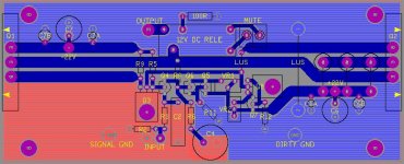
the yeuchhhh PCB
Hello Graham
That must be my Layout you talk about. but have no worry, its been testest. and after changing back to The Penultimate Circuit
it is stable whit 2 2SC2922 tranis and sound just fine.
But yes you are right it is not the optimal shape for a pcb. the thing is that i am building 2 mono block whit 1 heatsink on eatch side, so i need a long PCB to be able to mount the tranis directly to the heatsinks.
anyway here are my newest attemt. q3 and q8 are coled from the 10mm alu plate/bar the pcb is mouted on.
Attachments
more experiments:
1) the turn-on rush current doesn't seem to have anything to do with temperature of the mosfets. It is about 5a for a cold or hot start.
2) using a higher source resistors helps reduce the turn-on rush current, but not by much. With a 0.47ohm source resistor, I got about 4-5a turn-on rush current, vs. 5a for 0.2ohm.
3) the rush current has nothing to do with Iq. I tried 0.8amp, 1amp, 1.25am and 2amp Iq (on 0.2ohm source resistor). the turn-on rush current was about 5amp in all cases.
I am starting to think that some kind of choke in place of the upper source resistor may be the way to go in order to kill the turn-on rush current.
Any thoughts?
- Home
- Amplifiers
- Solid State
- JLH 10 Watt class A amplifier