tschrama said:I do have a turn-on bump.. I thing this is because the 15K/470uF bias stabilization
Thijs
I think you are right. At turn on, due to the cap (470uf), the base of the input transistor is tied to the ground. that means the DC output point (where the output cap is attached, and the drain of the upper mosfet). So through the boot trap resistors, there is a huge voltage drop off G and S of the upper mosfet, causing a big current rush (to charge up the output capcitor).
Does the BJT version behave like that as well? Sounds like it should.
just wanted to pass this onto you guys.
I used to describe my mosfet jlh1969 as "bouncy" in bass reproduction (no, not the fishy thing). while I was playing with it a couple nights ago in the garage, my wife stopped by and said its bass was "effortless". I think that is a far more accurate word.
we both also concluded that the jlh doesn't have any advantage in treble over my other amps (a parasound, a signature and a sony).
millwood said:we both also concluded that the jlh doesn't have any advantage in treble over my other amps (a parasound, a signature and a sony).
Interesting. This is at variance with the large amount of feedback I have received from constructors of the BJT versions who, by and large, praise the mid-range and treble qualities.
Geoff said:
Interesting. This is at variance with the large amount of feedback I have received from constructors of the BJT versions who, by and large, praise the mid-range and treble qualities.
if there is a difference in the high-end, you would think the mosfet would do better than the bjts.
I think one possible explanation is that the other amps are pretty good ones. I was actually surprised that the jlh did a better job on the low-end, given that the other amps are DC coupled and should in theory respond down to 0hz.
Geoff said:Thijs
Millwood
My preferred input bias arrangement for a single supply rail is attached. I don't know whether it will cure your switch-on thump though.
Geoff
i am not sure if it will do. I think it has higher input impedence than the orignal jlh. But the base of the input transistor is also tied to the ground at turn-on.
BTW, geoff, do people report turn-on thumps with bjt jlh1969 as well? I am curious if this turn-on thump thing is a mosfet thing.
For what it is worth.... I found acoustic bass of my BTJ JHL very nice indeed.. but it was the treble clarity that made the biggest inpresion.. Then later,I became to perceive the treble a bit too apparent..
The 30 min oflistening to my MOSFET version had the same bass quality: very live-like without being heavy, but the treble was a bit more 'easy going' or relax, without losing clarity ..
PS
I found a new advantage of te MOSFET version.. I will work just fine as a Class B or Class AB amplifier when you 'under-bias' the output stage... This is not possible with the BJT version .. (yep.. in essence again due to the difference in voltage v. current driven...") ..I think I actually am beginning to think about the MOSFET version as an upgrade.... still has to pass listening test though...
..I think I actually am beginning to think about the MOSFET version as an upgrade.... still has to pass listening test though...
 .. now lets see what went wrong with my version and re-build it..
gr,
Thijs
The 30 min oflistening to my MOSFET version had the same bass quality: very live-like without being heavy, but the treble was a bit more 'easy going' or relax, without losing clarity ..
PS
I found a new advantage of te MOSFET version.. I will work just fine as a Class B or Class AB amplifier when you 'under-bias' the output stage... This is not possible with the BJT version .. (yep.. in essence again due to the difference in voltage v. current driven...
..I think I actually am beginning to think about the MOSFET version as an upgrade.... still has to pass listening test though... .. now lets see what went wrong with my version and re-build it..gr,
Thijs
OK... I'm back.. again ...
I looks like I somehow were able to blow oneof the MOSFETs, the upper only functioned as a zener (?) of around 2.2V? Replaced it , and in no time got my amp up and running again.. but...
Still the same ringing! The amp is fast, it can produce a 500KHz quare wave still as being somewhat square... a 10KHz square wave looks perfect.. allmost .. the ringing is there,barely visible since its at ?700KHz? maybe even higher ... I tried a 390pF across the 1K FB resistor but now it has gone into spontanious oscilation at around 4MHz(?) ...
What should I do?
Regards,
Thijs
PS
the Ibias setting is troublelingme too, going from 28V to 30V the Ibias goes from 200mA to 600mA...
PPS
The turn up bumpis happening in the BJT version too,at least in mine. You might mionimuze it by choosing the appropiate value capacitors in the circuit, bigger is not always better...
"Do any of you have a better suggestion how to stabilize the amp in a simple way,safely?"
you could try 47pF between ip tr emitter and driver tr collector as a starting point.
JLH gives details of a more comprhesive network. it's a bit drastic but may be a safe starting point. This can be found on geoff's site
hope this helps
mike
you could try 47pF between ip tr emitter and driver tr collector as a starting point.
JLH gives details of a more comprhesive network. it's a bit drastic but may be a safe starting point. This can be found on geoff's site
hope this helps
mike
on the turn-on thump: this might be a place where the bjt version has an edge. a bjt is a current device. so to reduce the turn on, one can put a resistor in the base of the upper output device to limit the turn-on current. This will not adversely impact the efficiency of the amp.
a mosfet is a voltage device. so the only way to reduce turn on current is to put a resistor on the source of the mosfet. I used a 0.2ohm resistor and I estimated the turn-on current to be around 5 - 6 amps (I blew quite a few fuses to find it out,).
I surppose that with a larger resistor (like 0.47ohm used by tschrama), the turn-on thump can be reduced but at the expenses of lower output power and lower efficiency.
Looks like the resistors are a must for a mosfet jlh. I originally used them as a way to measure Iq. it "accidentally" saved me a lot of trouble and blown mosfets,
better be lucky than good.
a mosfet is a voltage device. so the only way to reduce turn on current is to put a resistor on the source of the mosfet. I used a 0.2ohm resistor and I estimated the turn-on current to be around 5 - 6 amps (I blew quite a few fuses to find it out,
).I surppose that with a larger resistor (like 0.47ohm used by tschrama), the turn-on thump can be reduced but at the expenses of lower output power and lower efficiency.
Looks like the resistors are a must for a mosfet jlh. I originally used them as a way to measure Iq. it "accidentally" saved me a lot of trouble and blown mosfets,
better be lucky than good.
GRollins said:Jbut my objection has always been that the Zout for the two halves differs widely; the top coming from the plate/collector and the bottom coming from the cathode/emitter (hence a follower). The difference in Zout can lead to disparities in frequenciy response between the top and bottom halves of the circuit at higher frequencies.
Grey
I am going through old posts in this thread to understand this a little better. the above post makes a lot of sense. If the differences in Zout are to be avoided, wouldn't that advocate the use of mosfet output devices because of their high input impendance (for now, forget about Ciss)?
Re: FET AMP!
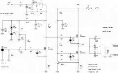
that's a slightly different design. the lower mosfet is a current source and the upper mosfet acts like a power follower. More like one of Pass' designs than JLH's push-pull class a.
Audiofanatic said:Hi Guys,
Try this one!
Best regards,
Audiofanatic
that's a slightly different design. the lower mosfet is a current source and the upper mosfet acts like a power follower. More like one of Pass' designs than JLH's push-pull class a.
I have gone through about 2/3 of all the old posts (not as thoroughly as I would have liked). I am surprised that many people seemed to have stability problems, as tschrama is experiencing. Is there any inherent issue with the circuitry as far as stability is concerned?
I have to see that I experienced none but I don't have a scope to look for high frequency oscillations so I cannot be 100% sure.
Also, tschrama, do you have access to an "unregulated" PS? I wanted to see if hum would be a problem for yours: it is not a problem for mine.
I have to see that I experienced none but I don't have a scope to look for high frequency oscillations so I cannot be 100% sure.
Also, tschrama, do you have access to an "unregulated" PS? I wanted to see if hum would be a problem for yours: it is not a problem for mine.
millwood said:I am surprised that many people seemed to have stability problems, as tschrama is experiencing. Is there any inherent issue with the circuitry as far as stability is concerned?
This little amp when made according to the original cct, with careful selection of transistors, and with a sensible layout is stable without any compensation circuitry.
however it also has a very wide frequency response and it does not, it seems, take much to push it over the edge into instability.
from my very recent simulation experiments paying particular attention to the effect various changes have on the gain/phase margins, I would recomend the following to make things better
don't decrease the feedback resistor values unless you take other measures to improve gain phase.
try a small increase of current through the i/p tr ie try making the 8.2K res 5.2 or 4.7K. for dc feedback cct's this will mean that you have to redo the dc offset by increasing the current in the ip stage CCS.
in fact an increase in standing currents generally should help but take care to notice that increasing the current in the driver cct by reducing the driver load resistor reduces the current in the o/p cct so this will have to be re-adjusted aswell.
reducing the impedence of the i/p filter also seems to help but be sure not to make it undrivable !
If for whatever reason the above does not do the trick with your implementation then it looks like a compensation network is needed. a good starting point would be a very small cap from ip tr emitter to dr tr collector.
the final solution would be impementing the full 3 element compensation stratagy as published by JLH and available of geoff's site. this is a bit drastic and could well be moderated as it increases hf distortion in it's original form and is way more than is necessary to sort out any problem in a fairly faithful implementation of the amplifier.
however from even my simulated experients I have realised that designing compensation networks is heady stuff that could well, if done incorrectly, make the problem even worse so extreme care has to be taken to avoid damage. I would not attempt this personally if I did not have a scope
hope any or all of this may help a bit
cheers
mike
PSU Voltage
Geoff and Millwood!
Thanks a lot for your answer.
What do you think: should I reduce the 30 V with power resistors, as in the Hiraga PSU's? Besides I got a Pi filter too.
Or: somebody wrote in the forum about to use a light bulbs in the AC rails to get lower DC voltage. Ofcourse I would get lower VA, but is there any calculation form to do this?
May be it would be good instead of a variac...
Thanks!
Well, I managed to blow another MOSFET.. again... happend while testing a 1MHz square wave at 20Vpp ... The square wave not pretty.. the falling egde has enopurmus overshoot.... at higher Iq things got only worse.... The spontanious oscilation is gone, it was output_to_input coupling and a bit neater arangementof the wires made it go away.... There is large HF overshoot but oscilation. My BJT behave nicely in this area, but I'm gonna check just to be sure...Originally posted by GRollins
Jbut my objection has always been that the Zout for the two halves differs widely; the top coming from the plate/collector and the bottom coming from the cathode/emitter (hence a follower). The difference in Zout can lead to disparities in frequenciy response between the top and bottom halves of the circuit at higher frequencies.
If we take this samekind of argument for the driver-output-impedance, then I agree for the MOSFET version. The two MOSFETs are driven from differning impedances and this make the HF behavior nasty..I think at least.. This might very well be the reason why current consumption goes up at HF (losing correct phase relation between MOSFETs) and the upper MOSFET keeps blowing ...
For the BJT case, I don't think it is a problem. Neither for the driving-part, as for the output-part...
Millwood,
I'm sorry to say that I don't have a suiteble unregulated pwer supply.
Greetings,
Thijs
I just tested the BJT version with square waves... again no oscilation,absolutely stable without any compensation capacitors, but some mild ringing on the falling edge, and severe assymetric slewrate...
Going to my simulator it was shocking to see has accurate the simulator predicterd the waveform on my scope... Both for the MOSFET version as for the BJT version, the spice output was very close to my actual wavefroms on my scope... complete with ringing/overshoot/assymetric slewrate ....
Regards,
Thijs
tschrama said:I just tested the BJT version with square waves... again no oscilation,absolutely stable without any compensation capacitors, but some mild ringing on the falling edge, and severe assymetric slewrate...
Going to my simulator it was shocking to see has accurate the simulator predicterd the waveform on my scope... Both for the MOSFET version as for the BJT version, the spice output was very close to my actual wavefroms on my scope... complete with ringing/overshoot/assymetric slewrate ....
Regards,
Thijs
Yes - but how does it sound !
by the way these amps have a reputation to sound good they don't look so good in simulation - you can rev it up so they look very good in simulation but I have yet to discover if this sounds good !
mike
I thought 30v is about right for the jlh so you don't need to reduce the voltage, unless you are running huge Iq on skinny transistors.
for the light bulb idea, be careful that their "resistance" is drastically different when cold vs. hot. you may have to experiment a little or use a multimeter to help you. another idea I think is to use heating elements you can get from home depot. It is a little easier for layout.
for the light bulb idea, be careful that their "resistance" is drastically different when cold vs. hot. you may have to experiment a little or use a multimeter to help you. another idea I think is to use heating elements you can get from home depot. It is a little easier for layout.
- Home
- Amplifiers
- Solid State
- JLH 10 Watt class A amplifier