I fully agree with Philipp on this.
And there's another problem with switching amps for esl: What do you think will happen in terms of radio interference when you connect an oscillator running at several 100 khz, producing steep flanks thus putting huge amounts of energy in high harmonics, with an output swing of several kV, to a very large antenna (your esl)...
I believe this is quite similair to the way Marconi bridged the Channel for the first time using radiowaves
Hi maudio,
I see you are experienced at this so i think you can help me a bit.
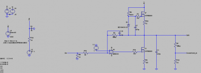
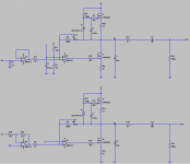
I have rebuilt my schematic.Instead of a resistor load , i used CCS.Bias is ~45mA. Also , i increased closed loop gain of the amp .It became by far easier to stabilise.
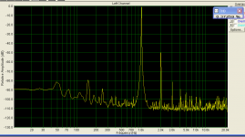
I observed really strange things happening with THD curves.
With resistor divinder to sound card = 200k/0.4k , full output swing :
At 10K , THD is only 0.003% !!!
At 1K , THD is 0.4 % !!
if divider is changed to 1Meg/0.4K :
At 10 K THD = 0.03 %
At 1K THD = 0.08 %
At 100Hz Thd = 0.3 %
For 200K i used 2 5w wirewounds in series , for 1Meg - 2Watt carbon one.Wirewound didn't limit frequency response at all.
If it was a problem with opamps incapable of driving MOSFETs , the THD would rise at high freqs , wouldn't it ?
Also i observed differences (rising distortion) , if i short the source resistor of Q1.
What can be happening ? Problems with rf filters in PC power supply , as you mentioned ?
Regards,
Lukas.
I see you are experienced at this so i think you can help me a bit
.I have rebuilt my schematic.Instead of a resistor load , i used CCS.Bias is ~45mA. Also , i increased closed loop gain of the amp .It became by far easier to stabilise.
I observed really strange things happening with THD curves.
With resistor divinder to sound card = 200k/0.4k , full output swing :
At 10K , THD is only 0.003% !!!
At 1K , THD is 0.4 % !!
if divider is changed to 1Meg/0.4K :
At 10 K THD = 0.03 %
At 1K THD = 0.08 %
At 100Hz Thd = 0.3 %
For 200K i used 2 5w wirewounds in series , for 1Meg - 2Watt carbon one.Wirewound didn't limit frequency response at all.
If it was a problem with opamps incapable of driving MOSFETs , the THD would rise at high freqs , wouldn't it ?
Also i observed differences (rising distortion) , if i short the source resistor of Q1.
What can be happening ? Problems with rf filters in PC power supply , as you mentioned ?
Regards,
Lukas.
Attachments
Hi Lukas,
<I observed really strange things happening with THD curves.>
The problem is in your soundcard, not in your amp.
Your soundcard is probably sampling at 44.1 or 48 khz. So it won't measure anything at all above 22 or 24 khz.
When measuring thd @ 1khz, your measurement will only include 2nd to 5th harmonics since the 6th is already at 32khz.
Similair, at 10 khz you're only measuring second harmonic distortion, all higher harmonics are outside frequency range of the soundcard.
So, the fact that you measure more thd @ 100hz than at 1khz may indicate that your amp produces a lot of higher harmonics (which is not good). But it may as well be that thd actually increases at low frequencies due to power supply noise (are you measuring thd or thd+noise).
The difference in results with the other divider are probably because the lower signal to the soundcard, increasing noise contribution.
Another consequence is that by using only soundcard, you can't be sure whether it's really stable or not since oscillations will be at frequencies way beyond what can be detected. But if you don't have an oscilloscope you can do crude oscillation detection by placing an AM-radioreceiver near the amp
<For 200K i used 2 5w wirewounds in series , for 1Meg - 2Watt carbon one.Wirewound didn't limit frequency response at all.>
The problem with high voltage over resistors is not in frequency limits but in non-linearity. A 1:100 divider will be 1:100 at 100V but this can easily change 20 or 30% at 1kv. That is, when using carbon oor metal film. Wire wounds probably won't have this problem but they do have a lot of inductance.
<Also i observed differences (rising distortion) , if i short the source resistor of Q1.>
That's because the source resistor provides local feedback linearizing the mosfet (the fet is controlled by Ugate-Usource, over the source resistor there is a signal proportional to output current, thus part of the output signal is subtracted from the input signal). So, when you add a source resistor the gain of the fetstage decreases but it becomes much more linear.
This tells you that most distortion is produced in the fet (not surprising, fets are very non-linear): Adding local feedback decreases total openloop gain so it also lowers the total amount of feedback. But obviously, local feedback around the fet pays off more than is lost by decrease of global feedback.
In general, using local feedback is a good way to lower distortion without running into the stability problems when using hig global feedback.
Unfortunately, with the source-follower configuration I used in the 4kV design it's impossible to use local feedback by adding a source R: the current coming from the source is not proportional to output current anymore
See that you can learn a lot about your creation even with a limited soundcard measurement system
Martin
invisible force said:Hi Martin,
suggestion :
D1 should be held conductive by a voltage source (Vbe multiplier ...) inserted between Drain of Q1and R1, D1`s kathode direct to drain of Q1, R2 removed.
The idea behind :
As the load is almost a pure capacity there should be no current for a moment when derivation of output is changing sign ...
If D1 could be made conductive at that moment threre should be no nasty current peak because of sudden charge of Q2´s gate source capacity..
Am I wrong ?
regards,
Philipp
Hi Philipp,
I hope I understood your suggestion well. I don't think it will work. The problem doesn't occur when the output current derivation changes sign, but when output current crosses the idle current setting. So, it will shift along the slope of the signal along with amplitude.
As I told before, I tried to reduce the problem by adding 220 u in series with a few hundred ohms between drain of Q1 and source of Q2. The idea behind is to create an alternatice pathway for the current, the C will maintain more or less Ugs level so the change in voltage over the diode will be much smaller. Since signal on the gate and source of Q2 is (almost) identical, it won't shortcurt the drive to Q2. Still, Q2 is turned of during part of each cycle and that is the main problem.
A better way would be to keep Q2 conducting all the time. I tried a thing or two but without much success before dropping this output configuration altogether, since will never meet safety demands anyway (drive voltage is relative to ground, so output will always carry 1/2 Vcc) so it will never result in a real practical amplifier.
Ideal would be a true push-pull output stage fed from symmetrical rail voltages: output at zero Vdc, low distortion. Among the things I considered to achieve this: stacking large amounts of low-voltage rated fets so P-channels come into view, or using optical drive to the output devices. But both have such practical problems that I never succeeded in getting it to work properly. Right now I am back at transformers and experimenting with enclosing them in the feedback loop.
But maybe someone comes up with a bright idea to overcome the difficulties with DD...
regards,
Martin
Bazukaz said:Hi,
The amp produces mainly 2nd harmonic.
Also there is a lot of noise , mainly 50 and 150 hz.I think it picks up mains hum somehow.
Also , i managed to blow one FET
Regards,
Lukas
Hi Lukas,
Indeed it looks mainly second... That's odd, by the way did you try measuring 'thd without noise'?
The only explanation I can come up with now for the strange thd curves is that your amp is oscillating. It would for sure explain the high figures you measure, with CCS load the fetstage will be quite linear and with an opamp in the path you have so much feedback applied that I'd expect thd to be in the thousands of a percent, if it was stable.
You write that it was easy to stabilize, but can you be sure... If I understand well, you don't have a scope available or am I wrong?
In fact, I am almost sure that your design can't be stable this way. Reason I am so sure is that I also started out using similair designs as you do now but I never got anything like it to work properly outside spice. They all proved impossble to stabilize.
You must lower openloopgain and you must add some frequency compensation (apart from c10). Skip the opamp, use an emittor follower to control the fet. It will work wonders.
Good luck and keep up the good work, much appriciation for your experiments!
Martin
(As long as there are more fets, there's hope)
Hi,
I have also experimented with this kind of circuit with BJTs as well.I have made a few experiments.Some of amps had the distortion , others not , with basically the same circuit.I haven't been able to detect the reason(once it dissapeared , by increasing supply caps ,but i wasn't able to repeat this).
I have came to several possibilities in my mind:
Problems with grounding ;
Oscillation;
Interference with sound card ;
Wrong main feedback resistor(2W carbon , 750V);
Interference with electrostatic fields created by relatively high voltages.
I have ordered some metal films , but i'll have to wait a couple of weeks until it arrives ...
I am not really sure about stability.It showed very good results in Spice , with very big tolerance to components.For sure , real world circuits may behave quite different , but i have found that spice is a good guide to find , what makes circuit more stable and what does not.
Thank you for helping me .
Best regards,
Lukas.
Bazukaz said:Hi,
I have also experimented with this kind of circuit with BJTs as well.I have made a few experiments.Some of amps had the distortion , others not , with basically the same circuit.I haven't been able to detect the reason(once it dissapeared , by increasing supply caps ,but i wasn't able to repeat this).
I think it is safe to assume that any such unpredictable behaviour is related to instability.
When using BJT's bear in mind safe operation area limits, a 1500V rated bu 508 for instance won't be any good over 700 V. That's why I use mosfets
I am not really sure about stability. It showed very good results in Spice , with very big tolerance to components.For sure , real world circuits may behave quite different , but i have found that spice is a good guide to find , what makes circuit more stable and what does not.
Spice is quite reliable for normal small signal circuitry with bjt or opamps, but in my experience you can't rely on it at all with this kind of design. It seems to understand very little about mosfet behaviour under these conditions. Almost anything you try in spice will be stable but in the real world it's very different.
You must have some way to detect hf-instability, otherwise you basically have no idea at all what's going on. You can use a detection circuit placed before your DVM (see picture) to do some basic detection. Connect to your amp (through divider) with no input signal applied, any reading other than zero indicates presence of hf oscillations. But then again this still won't tell you whether your design remains stable under load and with signal, or if it shows ringing etc. To be honest, you can't do without an oscilloscope here.
Thank you for helping me .
Best regards,
Lukas.
No problem!
By the way, do add some protection by means of a 12V zener between gate and source of all mosfets. Will prevent spikes from destroying them
Attachments
Hi,
Thanks for schematic.I have read 5-20mV readings after the bridge , but , even with amp disconnected from mains , i still get 5 mV , so i assume it is the accuracy limit of my multimeter.
If i leave input floating or connect it to ground , DIM reads around 0.6V.
If i connect to sound card , i get ~20mV , or less sometimes.
One more thing - they use carbon composition resistors as distortion generators ! And they produce 2nd harmonic - the same as i get ! And , in my case,the distortion increases inversely proportionally to frequency !
Even if i use carbon films , it seems that these may give such an amounts of THD easily , keeping in mind high DC voltages across it :
http://www.geofex.com/Article_Folders/carbon_comp/carboncomp.htm
One more thing:
I tried to watch at music signal in spectrum analyser.It seems that
, at >10 kHz , there is almost 30-40db less audio content , than ~200Hz. So , an amp with full voltage output capability to around 5-7kHz may work without current clipping(i think).
Regards,
Lukas.
I have read 5-20mV readings after the bridge , but , even with amp disconnected from mains , i still get 5 mV , so i assume it is the accuracy limit of my multimeter.
If i leave input floating or connect it to ground , DIM reads around 0.6V.
0.6 for sure means trouble. The other readings are strange, you are measuring DC I hope? Use a divider of 1:10, will give you much better signal to noise ratio when measuring.
Thanks for the link about resistor distortion, interesting article... I guess this is good news for the addicts of tube sound, a much cheaper way to produce their beloved harmonics
I tried to watch at music signal in spectrum analyser.It seems that
, at >10 kHz , there is almost 30-40db less audio content , than ~200Hz. So , an amp with full voltage output capability to around 5-7kHz may work without current clipping(i think).
You're right, but still you need around 50 mA to drive an ESL with 2000Vtt.
Regards,
Martin
Hi,
I think i have figured out the reason .. Sound card !
It is strange that is works well in loop configuration(out connected to in).
I set up Laptop PC for measurements , and all problems were gone.
THD+N fugure is now very realistic , showing 0.02% or less up to 7 kHz.At 1 kHz , THD+N is ~0.008%
IMD test results are similar.
Regards,
Lukas.
Hi Lukas,
that's good news. Under what load did you do these measurements?
Next step to extend it to a bridged amp, hook up your favorite esl and test it, to check that it not only measures good, but also sounds good
(yes, those are two different things)
Good luck, keep us informed..
that's good news. Under what load did you do these measurements?
Next step to extend it to a bridged amp, hook up your favorite esl and test it, to check that it not only measures good, but also sounds good
(yes, those are two different things)
Good luck, keep us informed..
Hi,
I measured it under 470pf load.I should have done with more , at least 1500pf , to get an idea how it works.By the way , IMD is around 0,015%. For comparison , LM3886 has only 0.004%. Is it bad , or shouldn't i care ? I guess it is the product of non-linear capacitance of FETs...
For now , i have problems obtaining mylar. I have made a wire ESL , and tried to use baking film , but is seems to be noisy ; PVC is by far too weak to hold any tension ...
www.audiocircuit.com sells mylar for 24$ , but only 10 metters - not so much for experiments ...
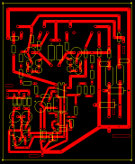
I have also drawn a PCB for this amp , it would be great to know what do you think about it.By the way , i included LEDs instead of zeners in CCS , and voltage regulated supply for op amps...
I hope to use mica insulators and avoid using standard screws with holes.The insulators are rated at 2kV.
Kind regards ,
Lukas.
I measured it under 470pf load.I should have done with more , at least 1500pf , to get an idea how it works.By the way , IMD is around 0,015%. For comparison , LM3886 has only 0.004%. Is it bad , or shouldn't i care ? I guess it is the product of non-linear capacitance of FETs...
For now , i have problems obtaining mylar
. I have made a wire ESL , and tried to use baking film , but is seems to be noisy ; PVC is by far too weak to hold any tension ... www.audiocircuit.com sells mylar for 24$ , but only 10 metters - not so much for experiments ...
I have also drawn a PCB for this amp , it would be great to know what do you think about it.By the way , i included LEDs instead of zeners in CCS , and voltage regulated supply for op amps...
I hope to use mica insulators and avoid using standard screws with holes.The insulators are rated at 2kV.
Kind regards ,
Lukas.
Attachments
Hi Lukas,
looked at your latest design, looks ok, some suggestions to think about:
- Very important: good hf decoupling. C2,6,7 should be bypassed with some small foil capacitor (0.1 u mkt). Also, place a small (10nf) foil capacitor (2 kv) on the pcb decoupling the hv supply. The electrolytic buffer caps in the power supply won't do much at higher frequencies, increasing risk of oscillations.
- R8/13 must be rated 1000V, did you take that into account? They also can be of much higher value than 1 meg, I used 18 meg without problems. Will decrease dissipation and will also make the current source behave much better.
- With large r8/13, C6/7 can be much smaller (100uf or even less).
- same for c2, a few uf will do.
- Again,you must add protection diodes (12 v zener) between gate and source of u1/4, anode to source, will save them from gate isolation breakdown when you start feeding signals containing steep slopes (aka music).
- Why need c1/4? I think you can safely omit them. They only drain current and you'll need every mA you can squeeze out of it.
- I would increase R14/21 to 1 or 2 kohm, won't affect frequency range at all and will increase stability a lot.
By the way, 10 meters of mylar seems like a lot to me. What do you intend to build
Your amp won't deliver enough voltage/current for a large panel anyway. I would suggest you build a small panel, maybe 15 x 100 cm surface area and also keep spacing from membrame to stator at <1.5 mm. Thighten membrame as much as possible, will allow for more bias thus better sensitivity. Otherwise your amp won't be able to drive it any louder than whispering levels... I know from experience.
Hi,
Thank you for suggestions.I will update the PCB and include HF decoupling caps.As far as i know , disc ceramics are the best for this purpose ...
One question : how is it possible , that FET gate could receive higher voltages , if op amp supply is only +-15 V ? IRFBG30 datasheet says , that max gate voltage is +-20V.By the way , i use these instead of IRFBG20 because of better availability in my city.
I included C1/C4 because it seems to stabilise circuit , at least in spice simulations.I could omit them , and rely on capacitance that will be formed between transistor and heatsink(grounded).If i would use mica , i would get ~140pF ; some thicker insulators would give less capacitance.
I have built a panel with capacitance of ~700 pF.(20x150cm).
I tried to simulate this load ; at 40 mA current , the amp can deliver
about 20%-25% less voltage(10kHz) , compared to 1 kHz. I think it should be enough , shoudn't it ?
I have also inspected the PCB and found a few errors.
Best regards,
Lukas.
Bazukaz said:Hi,
Thank you for suggestions.I will update the PCB and include HF decoupling caps.As far as i know , disc ceramics are the best for this purpose ...
One question : how is it possible , that FET gate could receive higher voltages , if op amp supply is only +-15 V ? IRFBG30 datasheet says , that max gate voltage is +-20V.By the way , i use these instead of IRFBG20 because of better availability in my city.
The danger comes from the other side: there are internal capacitances present in the mosfet. The one between drain and gate (~50pf) will transfer charge from drain to gate (this is also why you'd be better off with a emittor follower between opamp and fet, will prevent the charge from interfering with internal feedback mechanisms in the opamp).
Steep transients on the drain cause large spikes on the gate that can easily destroy it (dV/dT over Crss). Such transients occur in music but will also be generated by spikes on mains or in case of the inevitable small static discharges within the esl. You have only been testing with sine waves and with a very clean load so far, real life is very different. If you have access to a scope, try what happens on a 1 khz square wave, you'll be surprised...
.I included C1/C4 because it seems to stabilise circuit , at least in spice simulations.I could omit them , and rely on capacitance that will be formed between transistor and heatsink(grounded).If i would use mica , i would get ~140pF ; some thicker insulators would give less capacitance.
It will probably stabilize the circuit by reducing bandwidth. That can also be achieved with a small c over the opamp, this solution won't cost you any output current.
Again, better use seperate heatsinks. Will save you 140 pf additional load that drains output current you badly need for your panel, and will also increase reliability a lot. I have bad experiences with combining mosfets on 1 heatsink. If you insist on 1 heatsink try to get the special ceramic ones as pointed out by Netlist earlier in this tread.
I have built a panel with capacitance of ~700 pF.(20x150cm).
I tried to simulate this load ; at 40 mA current , the amp can deliver
about 20%-25% less voltage(10kHz) , compared to 1 kHz. I think it should be enough , shoudn't it ?
700pf is a lot to drive. But I suppose you'll be using segmentation? That will be necessary anyway, or it will bundle high frequencies too much.
Theoretically 40 mA may seem enough, but music isn't composed of sine waves. I measured peak stator currents up to 3 times what you'd expect based on capacitance, voltage and freq. Obviously there are more complex things going on here.
I think your panel is a bit large for this design, but again a lot depends on segmentation and your d/s spacing. You have to find an optimum, more d/s will provide more output SPL but will also require a lot more drive voltage (reduced sensitivity). What use is a 3 mm stroke if you can only drive it 0.2 mm...
So you have to match d/s to your drive voltage. In my experience 1 mm is about right for a 2kVtt amp.
Hi,
So , you really think that emitter follower would really improve things ?
Also , if i consider using it , i should add a diode from emitter to base , to protect it from op amp trying to drive it with negative voltages ?
One more : should i add zener from source to gate for CCS as well ?
About drive current :
Lets say , we have 4 ohm 100W amp with 10A current limit, driving ESL through 1:100 step-up.
So , max current at secondary is limited at 100mA. 1 nF load will look as 10 uF for amp; it has 1.6 ohm impedance at 10 kHz.So , I = 20/1.6 = 12.5A. We are already exceeding current limit of amp ! But it will be able to deliver much less than this , even much less that 10A , probably 2-3A in sine wave , because amp will have to dissipate all the power it delivers.
I made an assumption that amp characteristics are similar to LM3886.
Please correct , if i am wrong somewhere.
Best regards,
Lukas.
- Status
- This old topic is closed. If you want to reopen this topic, contact a moderator using the "Report Post" button.
- Home
- Loudspeakers
- Planars & Exotics
- Horizontal deflection (or high voltage type) transistors to directly drive ESLs?