Bazukaz said:Hi,
So , you really think that emitter follower would really improve things ?
Also , if i consider using it , i should add a diode from emitter to base , to protect it from op amp trying to drive it with negative voltages ?
Connect the emittor resistor to the negative power supply
") Allows the driver stage to deliver negative voltages as well, enabling it to discharge the gate capacitance of the fet faster.
Allows the driver stage to deliver negative voltages as well, enabling it to discharge the gate capacitance of the fet faster. Although the gate of the ccs fet is basically shortened to the source for AC, it won't hurt to do so. Won't cost much anyway.One more : should i add zener from source to gate for CCS as well ?
About drive current :
Lets say , we have 4 ohm 100W amp with 10A current limit, driving ESL through 1:100 step-up.
So , max current at secondary is limited at 100mA. 1 nF load will look as 10 uF for amp; it has 1.6 ohm impedance at 10 kHz.So , I = 20/1.6 = 12.5A. We are already exceeding current limit of amp ! But it will be able to deliver much less than this , even much less that 10A , probably 2-3A in sine wave , because amp will have to dissipate all the power it delivers.
I made an assumption that amp characteristics are similar to LM3886.
Please correct , if i am wrong somewhere.
LM3886, or for that matter, any amp limited to 10 A max won't do a very good job driving large esl's. I use a 130W/8ohm amp to drve my esl, it delivers over 20 A and can easily double that during short peaks. It does need it all when driving fullrange panels.
With direct drive you don't have to drive the transformer's internal capacitances saving a few hundred pf, but still...
Bobo1on1 is right that you don't need that much at 10khz. Energy content of music decreases, peak current drawn by the esl increases with higher frequencies. I found out that they indeed meet in the middle and that highest stator currents occur in the 1-4 khz range. To be on the safe side you have to be prepared for full output swing up to 4 khz, above that it drops quickly.
Anyway, 50 mA should be just about what's needed for a 2000Vpp design. I'm just wondering how you intend to handle the 100W heat disspation of your amp using only 1 heatsink
The assumption that the amp will not be able to deliver full current because it will have to dissipate all the power it delivers is something I cannot follow. The amp isn't delivering much real power at all because of the 90 degree phase shift caused by the esl (P=UI cos phi, cos 90=0). It just has to be able to deliver the peak currents and voltages needed. Or am I wrong here?
Talking about comparism: A 100W/8 ohm amp will deliver 28 V rms, that's 40 Vtt or 80 Vpeak to peak. So, connected to a 1:100 transfo there's 8 kV pp for the esl.
Your amp will deliver < 2 kVpp. That's 12 dB less music, the difference between 86 dB (pretty loud) and 74 dB (barely audible in a noise room). The only thing you can do about it is increasy sensitity of your esl, by lowering d/s spacing but that will limit low frequency excursion and will make it impossible to use the esl near it's resonance (read: below 100 hz). See my point that such an amp will not be able to drive large fullrange esl's..
You can get a lot of information by looking at the 1kv design I posted earlier. This amp isn't just something I draw on a rainy afternoon but it took a long time of trial, error and tweaking to get it to this point. So, it looks the way it does for very good reasons
Hi,
I plan to use large thick aluminium sheet as a heat sink and case.
Question about panel :
should i use a resistor between two segments ? How to choose its value ? Can an inductor be used there (i suppose its value should be large ?).
I made two segments with sizes approx. 6 and 13 cm( ~250 and 400 pF).
Note that only stator wires are segmented , the diapraghm is single.Is it ok ?
By the way , i borrowed a scope from my friend , and it seems that my sound card is oscillating (?) . If i zoom to very high frequency , there is a low-amplitude sine-like signal. Square is simply horrible.
The amp itself seems to have no oscillation problems , but clipping waveform is worse than simulated(there are small spikes when returning from ground-clipping).
To test square with it , i'll have to build a square generator , i think any op amp or comparator should work well.
Regards,
Lukas.
maudio said:
The assumption that the amp will not be able to deliver full current because it will have to dissipate all the power it delivers is something I cannot follow. The amp isn't delivering much real power at all because of the 90 degree phase shift caused by the esl (P=UI cos phi, cos 90=0). It just has to be able to deliver the peak currents and voltages needed. Or am I wrong here?
When using a normal amp with a resistive load the resistor uses power and dissipates it in the form of heat.
When using a reactive load the load doesn't dissipate any heat (ignoring some losses) instead the amplifier has to do that.
So when you want to supply huge currents to a reactive load the amplifier has to dissipate more power than it was possibly designed for.
But since this is a single ended class A amp it shouldn't matter much since it always dissipates lots of heat whether it has to deliver power or not.
Bazukaz said:Hi,
By the way , i borrowed a scope from my friend , and it seems that my sound card is oscillating (?) . If i zoom to very high frequency , there is a low-amplitude sine-like signal. Square is simply horrible.
The reason the square wave looks horrible is because of the very sharp lowpass in the oversampling dac, filtering out the harmonics that makes a square wave square.
The sine wave you see might be some interference from the computer's hardware, soundcard usually aren't shielded very well.
Bazukaz said:Hi,
I plan to use large thick aluminium sheet as a heat sink and case.
Talking about safety... Only a thin mica sheet between the case (you) and a very lethal 1000 V power supply. Hmmm. Be sure to ground every panel of the case thoroughly and seperately
 . Did you calculate required Rth of the heatsink?
Try to use a small (<5 cm) strip for high frequencies, a wider part for midrange and so on. Use as many sections as you want, will decrease bundling effects. Most esls use segmentation to smoothen out the effects of phase cancellation, which will give even output at all freqs but will not give optimal spreading. Ideally segment it in such way that every frequency is radiated by a section << its wavelength. But that won't give smooth freq curves so requires equalization by active filter.Question about panel :
should i use a resistor between two segments ? How to choose its value ? Can an inductor be used there (i suppose its value should be large ?).
I made two segments with sizes approx. 6 and 13 cm( ~250 and 400 pF).
Resistor value is easily calculated by r = 1/(2*pi*f*c). You don't need inductors at all.
yesNote that only stator wires are segmented , the diapraghm is single.Is it ok ?
bobo1on1 already explainedBy the way , i borrowed a scope from my friend , and it seems that my sound card is oscillating (?) . If i zoom to very high frequency , there is a low-amplitude sine-like signal. Square is simply horrible.
The amp itself seems to have no oscillation problems , but clipping waveform is worse than simulated(there are small spikes when returning from ground-clipping).
To test square with it , i'll have to build a square generator , i think any op amp or comparator should work well.
Make life easy on yourself and build it with some digital logic, 4093 CMOS oscillator will do just fine. Or use the good old 555... Next step could be to build one with adjustable duty cylce, the way the amp handles very small needle impulses often tells a lot about it's internals..
Recovering from clipping is one of those things that are likely to be troublesome with your design, openloop gain is very high so any clipping or slewing within the feedback loop will cause immediate saturation of something else (probably opamp output stage) causing slow recovery. Wait till you see your amp processing steep slopes, I suspect it will have quite some overshoot.
Now that you have a scope, try measuring bandwidth and see if there are any peaks in the transfer curve. You'll need a sine wave gen going up to a few 100 khz.
Hi,
So i have built a simple square generator with 555 timer.
I used the following schematic :
http://www.interq.or.jp/japan/se-inoue/e_ckt5_1.htm
Instead of resistors , i used pots.This allows to change the frequency from few hundred hertz to tens of kHz.
I used previous version , without emitter follower and gate protection zeners.the load was 3.8 nF to ground.Frequencies were adjusted between 1khz and a few khz.It is visible that slew rate is somewhat limited.
For higher frequencies (10kHz or so) , square turns into triangle due to slew rate limitation.
Now i think that not using an emtter follower has one advantage : the op amp has lower output inpedance and so can recharge gate of FET faster.If there is a clean square output , maybe i can ommit emitter followers ?.
Regards,
Lukas.
So i have built a simple square generator with 555 timer.
I used the following schematic :
http://www.interq.or.jp/japan/se-inoue/e_ckt5_1.htm
Instead of resistors , i used pots.This allows to change the frequency from few hundred hertz to tens of kHz.
I used previous version , without emitter follower and gate protection zeners.the load was 3.8 nF to ground.Frequencies were adjusted between 1khz and a few khz.It is visible that slew rate is somewhat limited.
For higher frequencies (10kHz or so) , square turns into triangle due to slew rate limitation
.Now i think that not using an emtter follower has one advantage : the op amp has lower output inpedance and so can recharge gate of FET faster.If there is a clean square output , maybe i can ommit emitter followers ?
.Regards,
Lukas.
Attachments
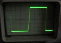
Bazukaz said:I used previous version , without emitter follower and gate protection zeners.the load was 3.8 nF to ground.Frequencies were adjusted between 1khz and a few khz.It is visible that slew rate is somewhat limited.
For higher frequencies (10kHz or so) , square turns into triangle due to slew rate limitation
3.8n is HUGE. Who not use something similair to your panel as load? Or even better, the panel itself (if you don't have mylar yet, no problem, you don't need a membrame for this).
Also, better use the full bridged amp with load connected between outputs instead of to ground. Will make a difference
And take a look at a square wave with the amp unloaded. Will tell you a thing or two about stability margins.
The square wave looks ok except for the thick horizontal line. Is that the picture being out of focus or is it oscillation?
By the way the most interesting place to measure is often the gate of the fet, but I believe you already found that out
Now i think that not using an emtter follower has one advantage : the op amp has lower output inpedance and so can recharge gate of FET faster.If there is a clean square output , maybe i can ommit emitter followers ?
That's not true: output impedance of the opamp will not be very low (the 0.3 ohm value on the datasheet is closed-loop, but you use it without local feedback around it). The emittor follower lowers it with factor hfe+1 (Zout = Zin/(hfe+1).
Additionally, the opamp uses some internal feedback (5532 uses 2 or 3 nested loops) that will couple signals forced upon its output back to it's internals. The emittor follower will largely prevent that.
By the way , there are very high amplitude sharp spikes at the gates of FETs , now i see why zeners are needed
Probably just luck?
No seriously, the IR fets will withstand much more than the datasheet ratings (I recently had a irfbg20 working at 1500V and it lives to tell the tale). Also, positive spikes on the gate are not so dangerous because the fet will switch on very fast reducing the spike. It's the negative ones that kill. For that reason, it might even be possbile to use plain 1n4148 instead of zeners. Benefit of normal diodes is that they are much faster than a zener. I used 1n4148 in the 4kv amps but somehow zeners give me more confidence.
Hi,
Thank you for suggesting the emitter follower . It seems to solve the negative clipping(spiking) problem.Again , not like in simulation.
I used a transistor(BC547) with base directly connected to opamp's out , and 1k emitter resistor to -15V.There is one problem left : in simulation , i can see that base of transistor can be driven negative in respect to emitter(about -7 Volts).Maybe the simple solultion would be to connect op amp's -VEE and emitter follower to GRND instead of -15V ?.
The blured lines are problems with the scope ; it is quite old , so can focus either horizontal or vertical lines, but not both at once.
Thank you for suggesting the emitter follower . It seems to solve the negative clipping(spiking) problem.Again , not like in simulation
.I used a transistor(BC547) with base directly connected to opamp's out , and 1k emitter resistor to -15V.There is one problem left : in simulation , i can see that base of transistor can be driven negative in respect to emitter(about -7 Volts).Maybe the simple solultion would be to connect op amp's -VEE and emitter follower to GRND instead of -15V ?.
The blured lines are problems with the scope ; it is quite old , so can focus either horizontal or vertical lines, but not both at once
.That's because the zener won't allow the gate to go any more negative than -0.7V. When the opamps pushes on even more negative the emittor can't follow (except for the small drop over the gate resistor).
No problem in practice because the opamp output will only go negative for very short peaks, when the opamp tries to switch off the fet fast and has to drain all charge from it's gate. This only happens when the gate is still positive.
Connecting opamp and emittor follower to ground instead will limit the ability of the driver stage to drain charge from the mosfet gate, when it can go negative it can put a larger voltage drop over the gate resistor.
Hi,
The negative voltages occur(in simulation) only when there is an overload.The op amp tries to push the output below ground , but , as you said , emitter follower cannot follow.
I was afraid that these negative voltages can degrade emitter follower transistor , but , if you say that this is not a problem ...
One more question : In your design , i saw that EHT supply is connected to middle point of voltage doubler , not ground.What is the purpose to do so ?
Thank you for helping me so much.
Best regards ,
Lukas.
One more question : In your design , i saw that EHT supply is connected to middle point of voltage doubler , not ground.What is the purpose to do so ?
Middle of the voltage doubler is at the same dc-level as the output. This is equivalent to the center tap of an ordinairy esl-transfo, allowing the use of the same eht supply as would be needed with a transformer.
You might as well connect the other end of the eht supply to ground or to +1kv, from an AC point of view it's all the same but it will give 500 v more or less bias on the membrame, depending on polarity.
Hi,
Yes , i understand this.
Because the best is to keep voltage negative on membrane (to prevent contacts from corossion) , i assume the most effeicient way would be to connect "+" of EHT to ground.
But what happens if EHT discharges to stator ? Would be there enough current to open FETs body diode ?
Yes , i understand this.
Because the best is to keep voltage negative on membrane (to prevent contacts from corossion) , i assume the most effeicient way would be to connect "+" of EHT to ground.
But what happens if EHT discharges to stator ? Would be there enough current to open FETs body diode ?
I never had a fet failure from such discharges. I guess the eht can discharge through the CCS (r3/12, gate protection zeners, r2/5, r1/11). The 499k resistors that are paralleling the power supply capacitors complete the path. Wow, that's indeed a good reason for using gate protection zeners for the upper fets as well. Never realized that before. Good thing I had them installed
What did happen to me a couple of times in my test setup is, when I switch on the eht with the input of the amp still floating, the entire amp builds up a charge relative to earth. Next, just touching the input will give a static discharge destroying the bc550 transistor at the input This because the amp is only grounded at the input.
But that can be easily solved by grounding the amp as it should be or by adding some overvoltage protection at the input.
What did happen to me a couple of times in my test setup is, when I switch on the eht with the input of the amp still floating, the entire amp builds up a charge relative to earth. Next, just touching the input will give a static discharge destroying the bc550 transistor at the input
This because the amp is only grounded at the input.But that can be easily solved by grounding the amp as it should be or by adding some overvoltage protection at the input.
Hi,
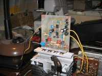
Here is the pic what i managed to build. After a few minutes , the thinnest mica insulator has bronken down, and fuse blew with a good sound. You were right about these insulators ... For some reason there developed a crack.
So i placed thicker ones , but these seem to have a considarable thermal resistance ( i measured about 1C/W !).
The large heat sink seems to be able to dissipate around 50W at ~70 degrees celsius. With some help , i think i could use it...
So with this i end up with ~90 Celsius on transistor cases(~15-18C more than heat sink due to insulator).Seems a bit highish ...
My the way , it seems that op-amps can survice high voltages at low currents at their inputs(650V through 1Meg ?).Do they have any kind of protection ?
Regards,
Lukas.
Here is the pic what i managed to build. After a few minutes , the thinnest mica insulator has bronken down, and fuse blew with a good sound
. You were right about these insulators ... For some reason there developed a crack.So i placed thicker ones , but these seem to have a considarable thermal resistance ( i measured about 1C/W !).
The large heat sink seems to be able to dissipate around 50W at ~70 degrees celsius. With some help , i think i could use it...
So with this i end up with ~90 Celsius on transistor cases(~15-18C more than heat sink due to insulator).Seems a bit highish ...
My the way , it seems that op-amps can survice high voltages at low currents at their inputs(650V through 1Meg ?).Do they have any kind of protection ?
Regards,
Lukas.
Attachments
90 degrees at the to220 case is not good for long term reliability I fear... Keeping in mind the derating factor of 1W/C 
Maybe you should try to find some of those ceramic washers. Or use 4 cpu coolers, in that case you won't need any insulation. The big ones (for amd athlon) can disspate quite some heat even without the fan running. I used them with the fan slowly running at around 3-5V instead of 12V, that's enough to cool away a Watt or 25 while still being very quiet.
Since your opamps are still alive, they probably have some protection Indeed I see 2 diodes over the input in the datasheet's internal schematic. Anyway, 650V over 1 meg is less than 1 mA so it probably can survive that
Maybe you should try to find some of those ceramic washers. Or use 4 cpu coolers, in that case you won't need any insulation. The big ones (for amd athlon) can disspate quite some heat even without the fan running. I used them with the fan slowly running at around 3-5V instead of 12V, that's enough to cool away a Watt or 25 while still being very quiet.
Since your opamps are still alive, they probably have some protection
Indeed I see 2 diodes over the input in the datasheet's internal schematic. Anyway, 650V over 1 meg is less than 1 mA so it probably can survive thatHi,
I tried to test it with square.
Why do you think a slight negative overshoot can appear?
Trying to watch with a scope shows much overshoot at emitter followers(not op-amp outs).
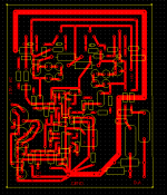
Some hum-like problems appear while trying to measure spectrum. Do you think the layout is correct ?
Regards,
Lukas.
I tried to test it with square.
Why do you think a slight negative overshoot can appear?
Trying to watch with a scope shows much overshoot at emitter followers(not op-amp outs).
Some hum-like problems appear while trying to measure spectrum. Do you think the layout is correct ?
Regards,
Lukas.
Attachments
Bazukaz said:I tried to test it with square.
Why do you think a slight negative overshoot can appear?
Trying to watch with a scope shows much overshoot at emitter followers(not op-amp outs).
Overshoot can be due to wrong value of the compensation C over the feedback resistor, it's value is very critical and that's why I made it adjustable
But the fact that you have negative overshoot only, and only at the gate, make it more likely that the steep negative slopes at the output are transferred through the drain-gate capacity to the gate. The emittor follower preventing it from reaching the opamp, as it should
Finally, it could be that the square is simply exceeding the slew limits imposed by max output current and load capacity. In music such steep slopes will not occur anyway.
In any case you can solve the problem with a slew limiting rc network at the input (see my design).
Some hum-like problems appear while trying to measure spectrum. Do you think the layout is correct ?
Layout looks fine to me, but a lot depends on external wiring and hv-power supply. What does it look like?
Hi,
Here i included the pic how i grounded everything.
I was able to reduce the overshoot at square ; it is now present only at one of outputs and is small.Clipping at 1 kHz is clear for both channels.
The best value for Gate resistor seems to be 200R.Trying to use larger resistance makes both clipping and square behaviour worse(more overshoot) , etc.
The mains hums mainly at 50 Hz seems a problem ; i wasn't able to detect what makes any difference at all.
By the way ,it might be a problem with sound card as well.
Regards,
Lukas.
Attachments
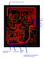
The only thing I can think of is that you try to connect all ground wires direct to central ground. But I don't think that will bring much. Ther might be a problem with to little buffer capacity (how much do you use?) but I would expect humm from the power suply to be at 100 hz not 50.
Anyway, if there is no audible humm when you connect the panel I wouldn't worry about it. It could very well be a problem with the soundcard, the inside of a pc isn't exactly a 'clean' environment in terms of EMC
Take a look at the spectrum of the soundcard with the input shortened
Overshoot at the outputs of the amp is something to avoid, it indicates peaking in the frequency domain which can lead to instability. At the gates there will always be some overshoot, which is logical since the output stage is the slowest stage in the amp (and sets the dominant pole).
Hi,
Thanks for all of your kind help.
I have measured the following :
Gate resistors decrease gate drive voltage;
Gate overshoot happens at point when drive voltage becomes lowest;
Gate overshoot is amost the same for both outputs;
At output , there is an overshoot when signal starts to rise , opposing to gate signals;
The signal generator(555) shows some ringing , though small , only visible when zoomed.
Overshoot is present only on one of outs , the one with longer output traces in PCB.
The weirdest thing , this is not very related with compensation cap , etc.
Best regards,
Lukas.
- Status
- This old topic is closed. If you want to reopen this topic, contact a moderator using the "Report Post" button.
- Home
- Loudspeakers
- Planars & Exotics
- Horizontal deflection (or high voltage type) transistors to directly drive ESLs?