Hello Martin,
this thread is interesting, indeed.I can strongly support your comments on pspice and MOSFET´s behaviour. The crux of the problem is the voltage dependancy of any semiconductor capacity (not only for HV circuits).
Has any one ever thought of dielectric absorbtion effects
inside a MOSFET ?
<The reasons behind are a long story, if anyone is interested pleae ask. >
I am interested. Respect for your 16 MOSFET amp, simply for the existance..
Do you mind sending me the circuit for discussion?
Having wound countless transformers for ESL´s I would state : The amplifier/transformer combination is the limiting factor regarding sound quality, therefore direct drive is the future here.
If you take a decent STAX earspeaker and connect it to a very good transformer / low voltage amplifier and compare it to a SRM-T1 direct drive (by the way : a current source instead of the anode resistors has proven to be a good idea for the SRM-T1) it is clear, what is better.
regards,
Philipp
Hi,
maudio :
I am very interested in building a direct drive amp.I was able to reduce distortion of previous amp to <0,5% at 100Hz (0,07% @ 1k).I think that 2Watt carbon resistors(750Volt type) may be the problem, because distortion is higher at lower frequencies.
I plan to drive ESLs that are quite sensitive.I think that 800V psu with bridged outputs should work , at least for a first project.
Here :
http://www.diyaudio.com/forums/showthread.php?postid=904846#post904846
I posted another schematic i have drawn; but even in Spice i can not stabilize it.I am not very experienced at this (.
(.
I would be great if you could share one of your schematics , not too complicated , if you have one.
Best regards,
Lukas.
maudio :
I am very interested in building a direct drive amp.I was able to reduce distortion of previous amp to <0,5% at 100Hz (0,07% @ 1k).I think that 2Watt carbon resistors(750Volt type) may be the problem, because distortion is higher at lower frequencies.
I plan to drive ESLs that are quite sensitive.I think that 800V psu with bridged outputs should work , at least for a first project.
Here :
http://www.diyaudio.com/forums/showthread.php?postid=904846#post904846
I posted another schematic i have drawn; but even in Spice i can not stabilize it.I am not very experienced at this
(.I would be great if you could share one of your schematics , not too complicated , if you have one
.Best regards,
Lukas.
Hi Phillipp and Lukas,
Phillip: I will answer your questions, but allow for some time... I also have to dig up the schematics, I build it a few years ago.
But I do include here the schematic of the 1kv design. It should work fine without too much trouble and the schematic is probably a good base for further discussions.
Some background information: I actually never designed this amp with the purpose of using it for driving my esl's, I rather built it to have a scaled-down version of bigger things to come without the additional problems of stacked output devices. It allowed for easy experimentation with different driver/feedback/etc configurations. But the end result is not bad at all for actually driving small esls or headphones.
The amp is a bridged single-ended class A design with current source loading. The 1 kV supply limitation is to avoid stacked fets.
Since there are no P-fets available for 1kv, I had to use N-types for the current sources. Which isn't the most elegant solution, the current needed for the voltage reference now flows into the output of the source. But by using leds as zeners I was able to reduce this current to 20uA so magnitude of this error is small. A current source built around a single mosfet this way isn't ideal anyway, but for this purpose it will do just fine. Amazingly this current source even turned out to be pretty stable, I never saw it oscillate.
As you see I don't use opamps but a current source loaded bc550 transistor as pre-stage. Together with the output stage gain there's plenty to achieve good thd figures.
Opamps add far too much gain here, to achieve good stability you have to reduce their gain in such a way that there is no point in using them anyway.
Performance:
Max output voltage swing is over 1900Vtt when ran from a 1kv supply. Output current is limited to 12 mA (quiescent current setting). THD is well below 0.1%, if I remember well I measured around 0.02% @ 1khz and around 0.08 @ 20khz between one output and gnd. So differentially (over the esl) distortion will probably be even lower. Don't expect to get much better numbers than this from any hv mosfet design (by the way Lukas, isn't the rise in low-freq distortion caused by your measuring software? Try increasing the fft-size).
Frequency range extends from a few hz (determined by C2) to around 60 khz (set by c9,c10 and the output devices internal capacitances).
The 12 mA output current will be sufficient only for a very small panel or headphone and the amp distorts heavily on larger panels due to current clipping. It is possible however to increase the current output (by lowering R3-12-4-10), if you also increase the power supply accordingly and provide enough heatsinking.
The practical limit of the design is around 40mA quiescent current, which will give a dissipation of 20W/fet totalling 80W/channel. This requires serious heatsinking (4 heatsinks each rated at < 1 C/W).
One way to get even more current would be to use the voltage drop over a resitor carrying the output current to modulate the current source (a bit like a SRPP) but it is very difficult to get this to work properly with a reactive load, let alone with complex loads such as a segmented wire-esl. Even if you do succeed in getting it to work, it will still only work for one very specific load. My experiences with it have been rather disappointing. You'll probably end up wasting a lot of extra heat in the output stage without getting much in return.
When posting a schematic like this I feel obliged to throw in some safety warnings:
- This is obvious NOT a newbies project nor a project for anyone without lots of experience in electronics, it uses lethal voltages and it CAN kill you. Use at your own risk and please take great care.
- Don't change anything or move measuring probes around while the circuit is live, use proper measurement gear rated for the voltages present. A 1:100 HV scope probe is well worth the investment.
- Each fet MUST have it's own heatsink. Mica of silicon insulation washers will fail sooner or later. Putting all fets on one heatsink might also give stability issues due to capacitive coupling between the fets, so don't.
- All heatsinks MUST be placed completely within the casing for safety reasons, no thermal washers will provide enough insulation to make the heatsinks safe to touch. You might want to consider forced cooling at higher currents. Cheap CPU coolers work excellent here, albeit a bit noisy.
- Be aware that this design puts a DC output voltage of 500V on the stators. For practical uses I would suggest adding 2 coupling capacitors with resistors to ground at the output, 10nf/2kv and 5*10meg in series should work fine.
This design shows in my opinion about the practical limits for what can be achieved using class A direct drive, in terms of output drive capabilities and dissipation. Disposing of any more heat in a safe way is impractical, especially since everything will have to be integrated with the esl panel, both for safety and to avoid EMC related trouble with your neighbours...
Looking forward to any reactions...
Martin
Hi,
Thanks for reply.
I am waiting for your schematic).
By the way , i think that it would be possible to use thick mica or silicone insulators , and ground the entire heat sink to improve safety.
I think that this method should give reliable and simple solution.
regards,
Lukas.
Thanks for reply.
I am waiting for your schematic
).By the way , i think that it would be possible to use thick mica or silicone insulators , and ground the entire heat sink to improve safety.
I think that this method should give reliable and simple solution.
regards,
Lukas.
Attachments
Would it be possible to use ceramic insulators as shownmaudio said:
- Each fet MUST have it's own heatsink. Mica of silicon insulation washers will fail sooner or later. Putting all fets on one heatsink might also give stability issues due to capacitive coupling between the fets, so don't.
here ?
Perhaps the thermal resistance is too high.
I recall building an amp where they were mandatory with regard to the capacitance.
/Hugo
By the way , i think that it would be possible to use thick mica or silicone insulators , and ground the entire heat sink to improve safety.
I think that this method should give reliable and simple solution.
Grounding the heatsink would prevent it from becoming live, but believe me, washers will most likely fail. Apart from sounding good you want your amp to be reliable as well...
The world isn't a perfect place and mica washers will have some microscopic pinholes, silicone washers when squeezed between heatsink and fet will have a spot a fraction of it's normal thickness (probably around the screw). All resulting in breakdown sooner or later.
The only option that will work is to use special ceramic washers, they do exist and are several mm thick (reducing capacity!) while still maintaining good heat conductance. Rated at 10kv or so. But they are hard to get and expensive.
Also remember that 4 small heatsinks can be smaller than 1 large because of better heat conduction to the air.
Using 1 kV on a irfbg20 is no problem at all, my experience is that these devices are very conservative rated and will withstand over 1200 V without any problems.
In fact, I never ever blew one that way. The only time I did destroy one was by letting it fry... (overheating)
Hi Martin,
Why not adding a source follower to the output - if it`s gate source connection is paralleled with a diode and kathode showing to the output Q1 and Q4 will sink the output current and the followers will provide the ESL with charging current. Idle current can be reduced significantly - less heat..Peak output current could be quite high by doing so.
regards,
Philipp
Bazukaz said:Hi,
I liked the idea to use PVC wire to make small caps very much
One question : why did you use 4x LEDs in series instead of a zener diode ?
Also , did you make any considerations to stop electrostatic fields from influencing signal paths ?
Lukas.
One has to be creative... You can also make good HV-c's from double sided printed circuit board.
I use leds because leds make a stable reference at much lower currents than zeners. The leds run at 20 uA, a zener wouldn't work at all at such low current.
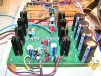
I did not shield anything in this circuit because it wasn't necessary, I can make a picture since the amplifier is still lying around here. But you're right, it's not a bad idea to use shielding, in fact with my 4000V designs it proved to be vital.
One more remark about your pcb design: you should move the gate-resistors as close as possible to the fets. When they are a few cm away they won't be able to do their jobs (which is to prevent parasatic oscillations). And no, I don't have a pcb design for my amp, I build it on breadboard.. I'll post a picture.
So this is what it lookes like...
Oh and I found an error in the schematic, please add 12V zeners between gate and source of the two bottom FETS for protection, will make them last a lot longer
I probably removed them from the schematic somewhere along the road because they tend to give troubles when running simulations, but you do need them.
Attachments
invisible force said:Hi Martin,
Why not adding a source follower to the output - if it`s gate source connection is paralleled with a diode and kathode showing to the output Q1 and Q4 will sink the output current and the followers will provide the ESL with charging current. Idle current can be reduced significantly - less heat..Peak output current could be quite high by doing so.
regards,
Philipp
Added a picture, makes it easier to explain:
Yes, that is in fact the only way to do it and I used this in my 4000V amp. When stacking 8 fets you can even do some clever things combining resistors. But there's a catch:
This concept will work fine while running in class A, quiescent current being determined by R1 and R2 (10 mA in each fet here). But now imagine what happens when the circuit has to sink more current than R2 can handle: This current has to be sinked by Q1 through D1 and R3. This means that the voltage over D1 has to make an immediate change from about +3V (Ugs for the Q2 when conducting) to -0.7V, requiring the gate capacitance to change charge very rapidly. Feedback will try to achieve this by putting a very large spike on the gate signal of Q1, probably causing overshoot unless everything is very carefully compensated and nothing saturates. The scope photograph shows what happens if you don't get it right.
And there's more trouble: when Q1 draws current from the load, Q2 stops conducting altogether since it is pinched of by negative gate voltage. That causes a considerable change in the impedance 'seen' by Q1, which in turn causes a large change in total gain causing even more distortion. What's worse, the behaviour of the output stage in the frequency domain changes along opening the road for instability.
Add to the bad news list that the fets are not so linear anyway in this application, probably because of the low currents in the mA range. Even in open loop such a stage build from 8 fets has about 20% thd running in class A. When it enters class B everything goes off scale and what comes out has very little to do with what goes in. This concept is excellent for digital driver application but not so ideal for linear use. But, it's the only way to build something using only N-channel fets.
So what can we do about it with some feedback: In fact, you have to deal with 2 output stages having very different parameters since the output stage is constantly switching between 2 very different conditions. This makes compensation awkward en puts limitations on the amount of feedback that can be applied since the circuit has to be stable in both situations.
All in all, not exactly a good base for a high-end amplifier.. It can be done, I reached thd figures of around 0.1-0.2 %, but it simply doesn't sound good. Especially in the midrange (where esl's need most current) it sounds harsh and I don't like it.
This concept also has the issue of having 1/2 Vcc on the outputs which for a practical amp for use in you living room is simply unacceptable. This can be solved with coupling capacitors but when these have to be rated at over 4000V things start to get tricky...
Hope you start to get the picture why it's not so easy to build a good direct drive
Attachments
Hi Martin,
suggestion :
D1 should be held conductive by a voltage source (Vbe multiplier ...) inserted between Drain of Q1and R1, D1`s kathode direct to drain of Q1, R2 removed.
The idea behind :
As the load is almost a pure capacity there should be no current for a moment when derivation of output is changing sign ...
If D1 could be made conductive at that moment threre should be no nasty current peak because of sudden charge of Q2´s gate source capacity..
Am I wrong ?
regards,
Philipp
For the brave-at-heart:
found a schematic of one of the bigger ones I built, do not try this at home It even produces soft music without the esl attached, I think because of ionization of the air between the heatsinks. Yes, that's scary.
I chosed to post this version because it shows all components seperate and includes the power supply. All others are more ore less simplified but this one gives some impression of the component count with such a design. How crazy can you be...
As I remember well, this specific one was optimized for maximum feedback in a futile attempt to minimize distortion. C8-9 are there to cancel out the first pole from the output stage allowing for some more feedback. With this I ran into the problem I described earlier, it is very tricky to keep things stable when the upper fets switch off and openloop parameters change. Stability margins were so narrow that it would start to oscillate when the load changed or even when it warmed up.
However, all versions use the same output configuration, differences were only in the pre-stages. You can built a pretty stable working version using a pre-stage similair to the one in the 1kV amp I posted earlier. But as I mentioned earlier, it doesn't sound good so don't bother. Apart from that, it's pretty lethal.
Phillip, I'll have to think about your suggestion, don't have much time now. Another solution I tried was to bypass D1 with a large capacitor in series with a small resistor. That works more or less (more less than more) but restricts bandwidth.
all good suggestions welcome!
have fun,
Martin
found a schematic of one of the bigger ones I built, do not try this at home
It even produces soft music without the esl attached, I think because of ionization of the air between the heatsinks. Yes, that's scary.I chosed to post this version because it shows all components seperate and includes the power supply. All others are more ore less simplified but this one gives some impression of the component count with such a design. How crazy can you be...
As I remember well, this specific one was optimized for maximum feedback in a futile attempt to minimize distortion. C8-9 are there to cancel out the first pole from the output stage allowing for some more feedback. With this I ran into the problem I described earlier, it is very tricky to keep things stable when the upper fets switch off and openloop parameters change. Stability margins were so narrow that it would start to oscillate when the load changed or even when it warmed up.
However, all versions use the same output configuration, differences were only in the pre-stages. You can built a pretty stable working version using a pre-stage similair to the one in the 1kV amp I posted earlier. But as I mentioned earlier, it doesn't sound good so don't bother. Apart from that, it's pretty lethal.
Phillip, I'll have to think about your suggestion, don't have much time now. Another solution I tried was to bypass D1 with a large capacitor in series with a small resistor. That works more or less (more less than more) but restricts bandwidth.
all good suggestions welcome!
have fun,
Martin
Attachments
maudio said:For the brave-at-heart:
found a schematic of one of the bigger ones I built, do not try this at home
I'm hoping to build a loudspeaker based on this concept
Hi,
Once i have had an idea to use class D ic amp and high frequency toroid as a step - up.I simply connected little ferrite toroid to amp's outputs , without a filter , with series resistor for protection.But i didn't get it work this way(saturating transformer ?).
Any suggestions ?
Once i have had an idea to use class D ic amp and high frequency toroid as a step - up.I simply connected little ferrite toroid to amp's outputs , without a filter , with series resistor for protection.But i didn't get it work this way(saturating transformer ?).
Any suggestions ?
- Status
- This old topic is closed. If you want to reopen this topic, contact a moderator using the "Report Post" button.
- Home
- Loudspeakers
- Planars & Exotics
- Horizontal deflection (or high voltage type) transistors to directly drive ESLs?