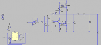
The emittor follower can sink source more current than it can sink, that's why it overshoots more in negative direction. Tells something about how much current is actually needed to drive the gate properlyHi,
Thanks for all of your kind help.
I have measured the following :
Gate resistors decrease gate drive voltage;
Gate overshoot happens at point when drive voltage becomes lowest;
Gate overshoot is amost the same for both outputs;

When it starts to rise or when it stops to rise? Maybe post a photograph?At output , there is an overshoot when signal starts to rise , opposing to gate signals;
That's a know problem with bipolair 555, better use a cmos version or experiment with different decoupling C's.The signal generator(555) shows some ringing , though small , only visible when zoomed.
Overshoot is present only on one of outs , the one with longer output traces in PCB.
The weirdest thing , this is not very related with compensation cap , etc.
Can be related to all kind of weird tricky not-in-the-textbook stuff, welcome to the wonderfull world of hv-amps
Anyway, this is difficult to judge from a distance. But as compensation has no influence you can probably rule out the feedback loop. Still, it might be interesting to know if gate overshoot is similair before and after the buffer, will tell you something more about where it is coming from (opamp-side or drain-gate capacitance or neither of those
 ).
).Some wild guesses you might look at:
- difference in fet parameters (HUGE tolerances here)
- difference in thickness of insulation spacers, do you have 4 identical ones
- capacitive coupling of some kind, probably between some high voltage swing point and some high impedance low level point. Heatsink has large capacitance, is it well grounded? Try shielding lowlevel section from high voltage section.
- Check input signals at both lowlevel inputs. Maybe the 5532 inverter stage is misbehaving (not likely)
All comes down to trying to isolate the problem. Both sections of your amp are almost identical, so focus on the differences.
Are you sure it IS a problem? Any amp will run into trouble at a certain slewrate limit, best way around that is to prevent such signals from reaching it with a slew limiting rc filter. There's no problem in limiting bandwidth to 50 khz, is there
regards,
martin
maudio said:Are you sure it IS a problem? Any amp will run into trouble at a certain slewrate limit, best way around that is to prevent such signals from reaching it with a slew limiting rc filter. There's no problem in limiting bandwidth to 50 khz, is there
regards,
martin [/B]
Hi,
Thanks for support.
No , i don't think it is a really big problem.
Today , i have finally managed to stretch baking film onto frame(~12 micron).I used tape used for sealing windows.By lots of tape, i managed to get quite good tension(as for such a method). I am not sure what is the resonant frequency ; i'd say somewhere from 70 to 100 Hz(for 1.5x0.2 m panel).I used a thin double sided tape to glue film to spacers. For condutive coating , i used shoe wax
So , how does it sound ? Not too quet , not very load.
The mids are clear. The highs are slightly cut off; 12 micron film may be too thick.
I am also having a leakage problem, but the panel is made easy to dissasemble , so fixing it should not be a problem.
There is absolutely no audible hum or any noise(except for very quet "click" sounds that come from various places of panel , when ear is very close).
I was also thinking about a simple overload detector with 555. A monostable application could be used."Trigger" pin would go to base of emitter follower. This would trigger the IC , if omamp out goes negative , and it would light a LED for some time. The main advantage that it would detect current clipping as well.Disadvantage : only positive voltage clipping is detected.
This would allow me to select the optimum current for CCS.
Best Regards,
Lukas.
Attachments
- Status
- This old topic is closed. If you want to reopen this topic, contact a moderator using the "Report Post" button.
