Calvin said:Hi Victim,
don´t guess..read! "Simply because they offer a superior signal handling in togetherness with an simpler and more straightforward design." At KR they´ve tried out several tubed driver topolgies, but always came back to the MOSed driver stage because of its simplicity and superior performance!
jauu
Calvin
Notwithsatanding my point that using another tube stage instead would have added a king's ransom or more to the amp price tag.
Hi,
Lets say , we can archieve an output voltage of 500Vrms , by using bridge. in case a 50:1 trafo is used with a 100W amp , it would give around 1kV rms..
Thats ~6db loader than 500Vrms.
By using higher voltage transistors(1.5kV fets or IGBs are not too uncommon , though not as easy to get as 1kV ones), we may approach 800-900Vrms , which is close to a 50:1 trannie.
I am not sure about your schematic , i think it is not good at all.There is one at www.shackman.de and one that i posted ...
Regards,
Lukas.
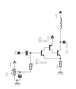
Those 3 transistors together should have a current gain of about 160.000, so unless you drive it with a very high impedance source there should be no problem at all.
Furthermore the amount of current needed to drive an esl is very low compared to a 8 ohm speaker.
Idle current will vary a little with T1's base-emitter voltage.
Furthermore the amount of current needed to drive an esl is very low compared to a 8 ohm speaker.
Idle current will vary a little with T1's base-emitter voltage.
") )
)Drive current
Hi,
for the full power bandwidth to reach 20kHz and beyond, You´ll need a couple of hundreds of mA of drive current. Of course may You fudge a little with the needed bandwidth (there´s not much signal above 10kHz) to reduce the current demand, but for a full fledged solution with a high capacitance panel (metal sheets) You should calculate with 300 to 500mA of peak current.
A topology I´m thinking about is like the Beveridge or the Acoustat Amp but using transistors instead and a µ-follower like Allan Kimmel´s instead of the Schmitt/SRPP stages. This should provide for a very linear class A-stage without the need for feedback (feedback maybe just for positive DC-centering?).
jauu
Calvin
Attachments
Well , for 300mA peak, and 1kV supply,
150W of idle power will be needed for one block.
If there are 2 bidged channels - thats 600W of steady power dissipation.A HUGE heatsink with fans , etc.
A dynamic tweeter , crossed at 2.5 kHz usually has a power rating of 1/10 of woofer's , or even less.
I dont think there is a need for so high current , unless panels are very highly capacitive.
Lukas.
bobo1on1 said:Wat type of inductor should I use? I was thinking about the ones that are used to start TL's, they should be able to provide a decent voltage without arcing.
Why do people constantly assume that everyone has the same brain wave patterns as themselves and understands their own pet acronyms sacrificing accurate communications of knowledge in the process?
On this forum the most likely meaning for the abbreviation "TL" would be "Transmission Line". They don't need starting with an inductor involving high voltage and steps to avoid arcing.
Could the poster please tell those of us here who are apparently ignorant, what the heck he means by "TL"?
Sorry, by TL I mean tube light.
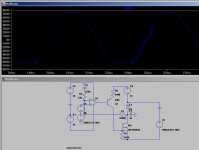
I ran a simulation using a resistor to keep the dc current accurate and a crossover to get a constant voltage above 10 hz or so, there is lots of oscillation, I don't think this is the way to go.
Also the panel and inductor will go in to resonance at a certain frequency.
btw the feedback is reversed in my previous schematics
Oops, made a mistake, used a 33k feedback resistor instead of 1M.
Anyway some steps should be taken to prevent oscillation.
Attachments
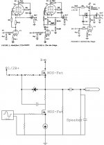
After running some simulations I think the best thing would be two good tubes, two 60 henry inductors and a 600 volt power supply.
Some feedback is also needed to damp the resonance between the inductors and the esl.
I wonder how big that inductor would be, I think it will have to be huge.
Some feedback is also needed to damp the resonance between the inductors and the esl.
I wonder how big that inductor would be, I think it will have to be huge.
Hi,
I was also thinking about the following.The cascode operation would allow for supply voltage of up to around 1.5kV by using 1kV FETs.A bridged version could give ~1kV RMS at output.
The problems would be limited power bandwidth and high power dissipation...
Regards,
Lukas.
I was also thinking about the following.The cascode operation would allow for supply voltage of up to around 1.5kV by using 1kV FETs.A bridged version could give ~1kV RMS at output.
The problems would be limited power bandwidth and high power dissipation...
Regards,
Lukas.
Attachments
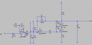
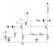
You need to connect R16 to gnd instead of the gate of U1, it now works like a weird kind of feedback.
Also 75k is a way too small value imho, you need at least 500k, of course this will limit the frequency response, so pherhaps some small caps in parallel to R16 and R22 would be wise.
Also 75k is a way too small value imho, you need at least 500k, of course this will limit the frequency response, so pherhaps some small caps in parallel to R16 and R22 would be wise.
What is the purpose to connect R16 to ground ?
I didn't invent this idea by myself , i found it at http://www.web-ee.com/primers/files/col_0412.pdf
The circuit shown is for JBTs , and i think it should be good for FETs too.
In simulations , it works well and shows f(-3) at > 100kHz.
Lukas.
I didn't invent this idea by myself , i found it at http://www.web-ee.com/primers/files/col_0412.pdf
The circuit shown is for JBTs , and i think it should be good for FETs too.
In simulations , it works well and shows f(-3) at > 100kHz.
Lukas.
HV-Amp
Hi,
I find this amplifier very interesting. Its designed as an integrated IC-solution to drive capacitive loads.
Therefore CMOS and DMOS technology is used on one wafer.
It should be possible to adopt this structure for disrete designs with higher voltages and power.
The structure is as follows:
A low-voltage CMOS difference amplifier (3) driving an inverter (5). A current controlled current source CCCS (4) is connected in series with the inverter with regard to the high voltage supply- looks similar to SRPP and alike concepts. The following high-voltage part is fabricated in DMOS technology.
The inverter output is connected to the input of a sourcefollower (6).
The SF is connected to the high voltage supply and the output of the circuit. A diode D1 is connected between the ouput of the circuit and the connection of inverter and CCCS to discharge the load capacitance when output signal level sinks.
jauu
Calvin
Attachments
- Status
- This old topic is closed. If you want to reopen this topic, contact a moderator using the "Report Post" button.
- Home
- Loudspeakers
- Planars & Exotics
- Horizontal deflection (or high voltage type) transistors to directly drive ESLs?