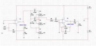
I tried the reverb but there is not enough drive from the Gibson scheme - it works but not well enough. I've revised the schematic, using an LM1875 as the drive device.
I made some other changes, in particular adding a buffer after the Master pot (as suggested by akis - thanks).
View attachment GUITAR PREAMP 2.pdf
Please look it over to see if I've made any of my stupid mistakes")
I made some other changes, in particular adding a buffer after the Master pot (as suggested by akis - thanks).
View attachment GUITAR PREAMP 2.pdf
Please look it over to see if I've made any of my stupid mistakes
Last edited:
I tried the reverb but there is not enough drive from the Gibson scheme - it works but not well enough. I've revised the schematic, using an LM1875 as the drive device.
I made some other changes, in particular adding a buffer after the Master pot (as suggested by akis - thanks).
View attachment 143093
Please look it over to see if I've made any of my stupid mistakes
Hi
Q5 also needs an R34 (additional to R33) to bias Q5, 50-50 ratio will do. However, I fear it is not that simple. Assuming the hfe of 2N5210 is 400 (if it is less then bin it) then with a rule of 10:1 the base resistor network of Q5 should be up to, but no more than, 40 * 2.2K = 88K, in other words R34=44K and R33=44K (or less) resulting in an input resistance of 22K at best. I do not know the value of "Master volume" pot, but it needs to be quite low to be able to drive the 22K resistance (ie it cannot be much over 20K, ideally 2K). That is why I typically put a FET following the pot, in other words replace Q5 for a good quality low noise FET (I use 2N5458 from memory - or was it 2N5459?), make R33 500K and the rest the same.
Also change C29 to something like 22uF else if you ever want to drive low impedances you will suffer bass loss.
Regarding the reverb unit I had also wanted to mention this, in my design I use a push-pull BC327/337 stage to drive it, I actually tested the impedance on my across different frequncies and it starts at 60R from low all the way up to a few K at high freqs., I have the notes at home, and again from memory, it requires something ridiculous like +/-4V to get something pitiful like 10mV at the other end… Also be careful with the grounding, I do not know which model you have bought, but typically the driver stage has a floating ground (a 47R resistance) and the springs unit has isolated inputs. The output is grounded on the chassis and you need something like 150x to hear what's coming out. As it mixes with the input signal it could positive feedback itself, so the choice of mixing resistors and therefore input buffers are crucial.
Akis (from work)
Hi
Q5 also needs an R34 (additional to R33) to bias Q5, 50-50 ratio will do. However, I fear it is not that simple. Assuming the hfe of 2N5210 is 400 (if it is less then bin it) then with a rule of 10:1 the base resistor network of Q5 should be up to, but no more than, 40 * 2.2K = 88K, in other words R34=44K and R33=44K (or less) resulting in an input resistance of 22K at best. I do not know the value of "Master volume" pot...
Also change C29 to something like 22uF else if you ever want to drive low impedances you will suffer bass loss.
Thanks,
I corrected the bias problem on Q5 almost immediately after I posted it.
I revised the schematic:
View attachment GUITAR PREAMP 2.pdf
I actually air wired the buffer to the prototype and it is fine. The "master" pot is 50k.
The power amp has ~30k input impedance so I don't see the need to increase C29.
I have made a new board layout. The dimensions are exactly the same as the prototype - I managed to fit everything fairly well. I'll etch it this evening:


I have changed my mind once again.
The latest preamp is assembled and working but I became sidetracked by a different one. While looking for possible designs to take inspiration from, I found mention of the Ampeg VH140C on the solid state guitar forum that Teemuk is a member of (here).
I looked it over and decided to take a shot at reproducing it. The schematics included a board layout and so I did it the hard way - started the board layout based on theirs and created a netlist as I went. Normally, the schematic would be captured and the netlist would come from that BUT I'm "the hard way" man of action so that's how I did it - the hard way.
Many hours, spread over many days (and nights) to produce the complete layout. A monster (for me) - board is 10cm x 36cm, too big for me to print and bigger that my biggest piece of PCB stock:

I decided to break it in two pieces, joined by a piece of ribbon cable.
Doable:

Thats the left side, channel "A" pots.
This is the right side, channel "B" pots plus the reverb send/receive circuit:

The line of pads on the right hand side of this are for connection to the chorus board (nearly as complex) which I'll be doing after this if assembled and debugged.
The latest preamp is assembled and working but I became sidetracked by a different one. While looking for possible designs to take inspiration from, I found mention of the Ampeg VH140C on the solid state guitar forum that Teemuk is a member of (here).
I looked it over and decided to take a shot at reproducing it. The schematics included a board layout and so I did it the hard way - started the board layout based on theirs and created a netlist as I went. Normally, the schematic would be captured and the netlist would come from that BUT I'm "the hard way" man of action so that's how I did it - the hard way.
Many hours, spread over many days (and nights) to produce the complete layout. A monster (for me) - board is 10cm x 36cm, too big for me to print and bigger that my biggest piece of PCB stock:
I decided to break it in two pieces, joined by a piece of ribbon cable.
Doable:
Thats the left side, channel "A" pots.
This is the right side, channel "B" pots plus the reverb send/receive circuit:
The line of pads on the right hand side of this are for connection to the chorus board (nearly as complex) which I'll be doing after this if assembled and debugged.
Hi,
Nice to see you are still at it! If you build this reverb/chorus you will be making something like the Fender Princenton Chorus, minus the distortion circuit. Chorus+reverb is a killer combination for harping and soft chords.
I am amazed at the easiness with which you are making PCBs
I am also very impressed with Multisim (which you introduced me to), it is a SUPERB product and saves a hell of a lot of trips to the workshop to make prototypes on breadboards etc. I wish I knew how to model the specific transistors that I am using though, I cannot make it understand that there are transistors with hfe=520 from 30uA to 10mA... If anyone here is an expert on Multisim this is a call for help
On my side I am 100% decided that "hard-wiring" ANY kind of tone control/effect inside the guitar amp box which weighs over 20Kg is NOT a good idea. The reason is that although you will always need a pair of good, loud speakers and a solid, good performing power amp, you will not know or can foresee what types of effects and tones you will ever need, or what type of guitar you will plug in. And during the course of a piece you will need to change the different effects, so that some kind of remote tone/effect control is paramount. Therefore it is best to let the guitar amp just do the "amp" part of the process and let other electronics deal with tone shaping. In other words, (almost) ditch the pre-amp, just a clean channel is what is needed.
I attach a couple of youtube links where you can see my son playing with his school band (Alex is 13) and you will see how often he "works" on the pedals he has on the floor. He completely bypasses any tone controls on the main amp, always uses either the "clean" channel or the "Return" plug.
YouTube - nothing else matters 15th October 2009 for senior school
YouTube - hotel_california_july_2009
YouTube - comfortably_numb_july_2009_take2
PS: I forgot to add what I am driving at!!!!
Instead of sticking the pre-amp inside the guitar amp box, which weighs a lot, and cannot be carried about on stage, why not make a floor-console-pre-amp-box which would house all the pre-amps and also provide a couple of foot switches to allow you to choose channels/effects/tones and some lights/indicators to show you what you have currently selected.
Last edited:
John
if you decided opamp way,
please ensure good decoupling of every power pin of opamps, to common gnd point (if possible), unless you will get noise and hum (IMHO - I experienced this).
I am astonished of you urge for perfection and working!
Thanks,
I figure if it's worth doing, it's worth doing well.
When I divided the board in two, I added extra PS decoupling and bypass:

This layout is nearly identical to the Ampeg layout so I shouldn't have any problems. But if I do, I could easily tack on a few bypass caps where needed.
Hi,
Nice to see you are still at it! If you build this reverb/chorus you will be making something like the Fender Princenton Chorus, minus the distortion circuit. Chorus+reverb is a killer combination for harping and soft chords.
I am amazed at the easiness with which you are making PCBs
First I must say your son is an excellent player

I see what you are saying about the tone / effects and that's an excellent idea - putting the pre in a separate unit. I want a "complete" amp though, all in one with the capability of adding other effects if desired. Once finished, this will most likely not get a lot of use and not be lugged around too much.
As for the PCBs, I have a LOT of practice
Update!
I have the Ampeg preamp clone built and working.
I have some pics to show.
The component sides:

The solder side, boards neatly tinned:

I had some space so I added a trademark:

Some more detail:

Like I mentioned, it seems to work properly, at least from a measurement standpoint. I want to run some music through it to see how it sounds (still don't have a guitar).
I've started work on the chorus board. This time I'm doing a schematic capture before I do the board layout - maybe save myself some grief.
I have the Ampeg preamp clone built and working.
I have some pics to show.
The component sides:
The solder side, boards neatly tinned:
I had some space so I added a trademark:
Some more detail:
Like I mentioned, it seems to work properly, at least from a measurement standpoint. I want to run some music through it to see how it sounds (still don't have a guitar).
I've started work on the chorus board. This time I'm doing a schematic capture before I do the board layout - maybe save myself some grief.
Looks great. Those pots must have cost a fortune.
For the PSU my advice would be to be generous with the filter caps, there is a ton of difference it makes to the low frequencies (eg when you strum a chord). From the 3 amps in Alex's bedroom (Fender, Vox, mine) , it is mine that has the deepest bass sound, the most full sound. And you can test this on a dummy load and a 15Hz frequency, drive it to clipping point and then check the gain, repeat for 1KHz and see whether the gain is materially diffferent. If yes then you need bigger caps.
I have also noticed that guitar amps do crazy things with "high" frequencies (in guitar terms that will be anything over 600-900Hz I suppose). It seems to me that the treble tone control of any decent guitar amp acts like a volume knob, it adds another dimension to the sound of the guitar, almost as if you are plucking closer and closer to the bridge.
Most importantly, it seems to me that if the guitar amp has a "clean" channel, well, it is not clean at all, it probably boosts treble by 100% (or chops bass frequencies, same thing). I need to do some simulations to work it out.
I am not very happy with Mustisim, very hard to get it to work reliably and slow as hell, very, very hard to test high frequencies (say 10K). I will try other simulators to see if there is anything better out there.
Thanks akis,
The pots were around $2.50 each so 10 are getting up there. I still need 5 more for the chorus board...
Earlier in this thread (post #49) I did some rudimentary tests with the power supply and didn't see significant sag at low frequencies. The transformer is quite hefty and I don't think I've got any worries there.
The preamp has a "clean" channel but I'm not sure just how clean it is. I want to find time to run it with music as the source to see how it sounds, maybe I'll find the time later in the week.
I continue my capture of the chorus board schematic - it's slow going but I'm almost there. It's a strain on the eyes to go from screen 10 feet away to printed 8.5" x 11" sheet in my hand. It's the kind of situation where 2 monitors would be handy. With a little determination I should have the board laid out by the weekend. I have ordered the 2 parts i can't get at Digikey - the MN3007 and MN3101 from an Ebay seller in Hong Kong - 10 of each for $35 gives me some to play with (or ruin).
Multisim I have no problem with. I love the interface and can't imagine using LT4 to do something like this. I don't know why you would be having difficulties - how fast is the computer you are using?
The pots were around $2.50 each so 10 are getting up there. I still need 5 more for the chorus board...
Earlier in this thread (post #49) I did some rudimentary tests with the power supply and didn't see significant sag at low frequencies. The transformer is quite hefty and I don't think I've got any worries there.
The preamp has a "clean" channel but I'm not sure just how clean it is. I want to find time to run it with music as the source to see how it sounds, maybe I'll find the time later in the week.
I continue my capture of the chorus board schematic - it's slow going but I'm almost there. It's a strain on the eyes to go from screen 10 feet away to printed 8.5" x 11" sheet in my hand. It's the kind of situation where 2 monitors would be handy. With a little determination I should have the board laid out by the weekend. I have ordered the 2 parts i can't get at Digikey - the MN3007 and MN3101 from an Ebay seller in Hong Kong - 10 of each for $35 gives me some to play with (or ruin
).Multisim I have no problem with. I love the interface and can't imagine using LT4 to do something like this. I don't know why you would be having difficulties - how fast is the computer you are using?
Thanks akis,
The pots were around $2.50 each so 10 are getting up there. I still need 5 more for the chorus board...
Earlier in this thread (post #49) I did some rudimentary tests with the power supply and didn't see significant sag at low frequencies. The transformer is quite hefty and I don't think I've got any worries there.
The preamp has a "clean" channel but I'm not sure just how clean it is. I want to find time to run it with music as the source to see how it sounds, maybe I'll find the time later in the week.
I continue my capture of the chorus board schematic - it's slow going but I'm almost there. It's a strain on the eyes to go from screen 10 feet away to printed 8.5" x 11" sheet in my hand. It's the kind of situation where 2 monitors would be handy. With a little determination I should have the board laid out by the weekend. I have ordered the 2 parts i can't get at Digikey - the MN3007 and MN3101 from an Ebay seller in Hong Kong - 10 of each for $35 gives me some to play with (or ruin
Multisim I have no problem with. I love the interface and can't imagine using LT4 to do something like this. I don't know why you would be having difficulties - how fast is the computer you are using?
$2.50 sounds cheap - over here I guess it would be like $6-10 US each... I live in this 3rd world country called "England"...
I ran a multisim of my own design tone controls last night, and it sucks. Doing completely the wrong thing. I will try to model the Fender controls this evening to get an idea.
I have started another thread (somewhere hereabouts) talking about simulators, what I do not like in Multisim is the way it models transistors but I have recently found some models dating back to 1996? and it seems better. I have a super fast PC, 4 cores, 3.2GHz, but Multisim is single threaded and trying to simulate over 3000Hz gets painfully slow. The interface is great you are right. I tried LTSpice and was in shock.
Bought Alex a Roland Juno Di for Christmas (keyboard) now I need to build an amplifier for it as the guitar amp cannot do the high frequencies...
I ran a multisim of my own design tone controls last night, and it sucks. Doing completely the wrong thing. I will try to model the Fender controls this evening to get an idea.
My design sucks in this respect, not multisim
Member
Joined 2009
Paid Member
OK I have analysed the Fender tone stack. Did not bother with the "middle" control, only Bass and Treble. Here is a table. Input signal 100mVp. Output givcen in mvp as well.
Code:
Fender tone stack		input 100mvp
	Bass 0	Bass 50	Bass 100
20	100	1084	1500
88	75	1000	1000
165	150	600	600
330	180	300	300
660	220	200	180
1320	400	340	340
2000	556	512	512
4000	953	932	932

	Treble 0	Treble 50	Treble 100
20	1140	1084	1004
88	1120	993	895
165	732	627	542
330	420	315	240
660	262	190	238
1320	202	333	571
2000	190	512	890
4000 190 933 1654OK it is a bit mis-aligned but easy to read. As I am lookimng at this for first time, trying to decipher some of the magic that makes a guitar amp a guitar amp, a special beast, and not a home steroe system onto which we have plugged in a guitar.
The frequencies in Hz, are on the left. 330 is open E on 6th string. 660 is 12th fret on the E 6th string, 1320 is 24th fret (if your guitar has it). 2000 and 4000 are for harmonics. 88 is open E 1st string. Some people tune their guitars to B but whatever, I did the 20Hz to cover everything.
It seems the "treble" knob starts having an effect at 1320Hz, with a ratio of 2.8:1. At 4000Hz (which is more or less what a reasonable guitar speaker can do), the ratio is 8.7:1.
The "bass" knob starts at 330Hz, with a ratio of 1.8:1. At 20Hz the ratio is 15:1.
It also seesm there is a hard-coded, permanent dumping of the "middle" frequencies between 165-2000Hz
Based on the above we can design a tone control stack to exhibit similar behaviour in some better documented way. I will try to do that in the following days. I also attach the simulation schematic for whoever wants to see what the Fender tone stack froma Princeton Chorus looks like.
Attachments
Last edited:
OK it is a bit mis-aligned but easy to read. As I am lookimng at this for first time, trying to decipher some of the magic that makes a guitar amp a guitar amp, a special beast, and not a home steroe system onto which we have plugged in a guitar.
The frequencies in Hz, are on the left. 330 is open E on 6th string. 660 is 12th fret on the E 6th string, 1320 is 24th fret (if your guitar has it). 2000 and 4000 are for harmonics. 88 is open E 1st string. Some people tune their guitars to B but whatever, I did the 20Hz to cover everything.
It seems the "treble" knob starts having an effect at 1320Hz, with a ratio of 2.8:1. At 4000Hz (which is more or less what a reasonable guitar speaker can do), the ratio is 8.7:1.
The "bass" knob starts at 330Hz, with a ratio of 1.8:1. At 20Hz the ratio is 15:1.
It also seesm there is a hard-coded, permanent dumping of the "middle" frequencies between 165-2000Hz
Based on the above we can design a tone control stack to exhibit similar behaviour in some better documented way. I will try to do that in the following days. I also attach the simulation schematic for whoever wants to see what the Fender tone stack froma Princeton Chorus looks like.
Guys,
Since you are MOA's (men of action) - I thought I better help save you
some precious time.
Download
You can also change the component values to "roll your own" and see the
results.
The typical passive guitar amp tonestacks tend to work better with minimal
OP loading.
Have fun
Terry
- Status
- This old topic is closed. If you want to reopen this topic, contact a moderator using the "Report Post" button.
- Home
- Live Sound
- Instruments and Amps
- Guitar Amp Design / Build