Hi MJL21193,
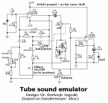
You might consider to try, and maybe, add this little unit in your guitar amp. A friend of mine built the prototype of this design few months ago. He is a service man for professional musicians equipment and very skilled in DIY. He also have a lot of guitarists coming frequently and he asked them to evaluate this “add on”. Most guitar players says that it sound nearest to “the real thing” i.e. tube amp, better than most tube-emulators they came over before. Honestly, I personally never heard that unit… that friend asked me to try to design something for that purpose but I haven’t got time to assemble and test it myself.
You might consider to try, and maybe, add this little unit in your guitar amp. A friend of mine built the prototype of this design few months ago. He is a service man for professional musicians equipment and very skilled in DIY. He also have a lot of guitarists coming frequently and he asked them to evaluate this “add on”. Most guitar players says that it sound nearest to “the real thing” i.e. tube amp, better than most tube-emulators they came over before. Honestly, I personally never heard that unit… that friend asked me to try to design something for that purpose but I haven’t got time to assemble and test it myself.
Attachments
HP 3050 with genuine toner from HP. I haven't used any other toner.
Power supply for the guitar amp:
View attachment 142539
I have a 27-0-27 transformer, probably in the neighbourhood of 200VA that I'll use for this.
This gives ~35VDC for the power amp and preamp plus +/-12V regulated for the other "accessories".
The amp module will be one of my Patchwork amps that is sitting around, collecting dust. This is an excellent use for it.
As a suggestion, and something I did on my amp, why not use a separate transformer for the pre-amp, so no matter what the big amp does the pre-amp remains (mostly) immune? In other words instead of trying to act after the "damage" has happened, why not try to prevent it altogether?
Also what is the nature of the parallel resistors, I do not understand that.
Thanks Khron, that article is interesting and I will look at modifying the amp module to operate that way. The method looks fairly simple.
I have the power supply finished:
View attachment 142633
Works as expected but I did have to substitute 15V regs in place of 12V, I had some (supposedly from ST) that I used but the negative reg (7912) seems to have a different pin out. My board is laid out for the standard >GND<>IN<>OUT< for pins 1,2 and 3 but the one I used (and another that I replaced it with) MUST have a different pin pattern.
No matter now, I've switched both for 15V and all is well.
Here's the PS running my Abomination amp:
View attachment 142641
It's driving an 8 ohm dummy load and I'm seeing 19.2Vrms output just before clipping and the rail voltage is down to +/-32VDC. This translates into ~50 watts into 8 ohms and (further testing will reveal) nearly 100 watts into 4. That should be enough power.
whoops you already built the PSU. Are these 22,000uF capacitors as per schematic? They look awfully small
Whoops again, 2,200uF they are, my bad
Last edited:
OK I am trying to work this out. After the first filter on your PSU, and with no load, you should have like 44.6V DC. But you have added the 2.2R and you say you have measured 35 VDC. Are you then dropping almost 10 volts on those resistors with no load? How is this possible?
Also, when you start pulling amps, there is ripple out of the first caps. I am not sure how effective the 2.2R / C is, but the ripple voltage entering it would be like 5.32V p2p (at 100W/8R and 100% efficiency ). At that point, no matter what the DC Voltmeter shows, it is not true. There is a base of 38.08 Volts on top of which the 5.32V ripple is added (like a hat) and the DC voltmeter would likely measure some average, ie bluntly, (38.08 + 5.32/2) or maybe (38.08 + 5.32/sqrt(2))/. But I cannot calculate the effect of the 2.2R/C filter.
Would you please mind running some tests to show the ripple in and the ripple out (past the 2.2R) ?
Also, when you start pulling amps, there is ripple out of the first caps. I am not sure how effective the 2.2R / C is, but the ripple voltage entering it would be like 5.32V p2p (at 100W/8R and 100% efficiency
Would you please mind running some tests to show the ripple in and the ripple out (past the 2.2R) ?
Hi MJL21193,
You might consider to try, and maybe, add this little unit in your guitar amp.
Thanks, where to place it? Between preamp and power amp?
I'll use this, just need to capture in Multisim and do up a board.
The Patchwork module running, mounted on the heatsink I'll use for this:
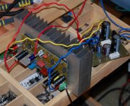
This is an older one with clamping diodes to prevent sticking during clipping.
I'll completely enclose the amp (a few vent holes) in a sheet metal case that'll attach to the heatsink.
Last edited:
Whoops again, 2,200uF they are, my badHmm is that not a bit low for all those amps (100W/4R) ?
The final design is below - I changed a few things:
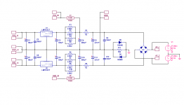
I don't think the cap values are too bad, considering the purpose - a guitar speaker won't be providing much bass, so really no need for a reserve of current.
OK I am trying to work this out. After the first filter on your PSU, and with no load, you should have like 44.6V DC. But you have added the 2.2R and you say you have measured 35 VDC. Are you then dropping almost 10 volts on those resistors with no load? How is this possible?
Also, when you start pulling amps, there is ripple out of the first caps. I am not sure how effective the 2.2R / C is, but the ripple voltage entering it would be like 5.32V p2p (at 100W/8R and 100% efficiency). At that point, no matter what the DC Voltmeter shows, it is not true. There is a base of 38.08 Volts on top of which the 5.32V ripple is added (like a hat) and the DC voltmeter would likely measure some average, ie bluntly, (38.08 + 5.32/2) or maybe (38.08 + 5.32/sqrt(2))/. But I cannot calculate the effect of the 2.2R/C filter.
Would you please mind running some tests to show the ripple in and the ripple out (past the 2.2R) ?
The AC from the transformer is 27 volts, the DC after the rectifier is ~38V. The resistor was changed to 1 ohm (what I had on hand) and is there for RC but also it's slight inductance. It does make a difference to ripple in the simulation. The amp this will supply has excellent ripple rejection.
I did look at ripple on the regulated supply and it is way, way down.
Hmm I thought I replied and the post is not here, strange. I will retype 
In the UK many transformers are 230V but mains is 240V, plus regulation (8.5% in your case) would raise the offload voltage considerably. 38 volts sounds quite low for off-load, my calcs show it as 40.83 volt, assuming you have 110V mains and 110V transformer.
The bit about ripple, on the guitar the top E is 80Hz and on the bass guitar 40Hz. I think there are 5 string bass guitars with an extra B below the E, that would be even lower. I am not sure how the 7 string guitars tune. And then you have harmonics too.
A nice test would be to inject a 40Hz signal and see what happens at full throttle on your dummy load. Is there attenuation compared to a 1KHz signal (for example). Are there 120Hz components in the output?
Oh, and I forgot, what is the nature of those parallel resistors? Why not just one? Increased wattage?
Did you include diode drops from the bridge in your voltage calcs?
The 40Hz signal has no effect on the supply voltage droop - same at 40 as it is at 1k. I may have under rated the transformer, it may be more than 200VA. In any case, there doesn't seem to be a lack of current.
As for 120Hz components, nothing that shows on the scope.
The parallel R's are for power dissipation. I don't have larger value 2 or 3 watt resistors on hand so this does the trick nicely.
Of course between preamp and power amp... where else! It could happened that you don’t need any gain in the last stage (U2), but don’t omit it… wire it as a buffer (short R11 and don’t use R12). Also, don't forget decoupling caps on supply pins of those OPAMP-s! They are not on schematic but I presume, everyone experienced will add them in a practical circuit.Thanks, where to place it? Between preamp and power amp?
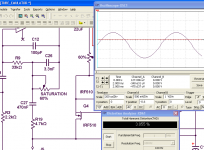
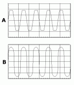
I spent some time fooling around with the tube emulator. I thought about how it could be changed to shift the distortion to even ordered, specifically H2 and H4. I looked at the MOSFETs and thought about adding some bias to see what happens.
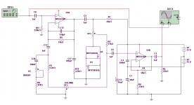
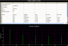
I made a few other changes and the >simulated< results look good. The crossover-like distortion is gone and the distortion spectra looks better:
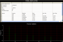
I tried it through different settings on the pots and always the lower order harmonics are stronger than the higher order.
I wonder how it sounds?


I made a few other changes and the >simulated< results look good. The crossover-like distortion is gone and the distortion spectra looks better:

I tried it through different settings on the pots and always the lower order harmonics are stronger than the higher order.
I wonder how it sounds?
Another thing I had wanted to comment on, but never had time, is on the pre-amp schematic there seems to be a strange economy on buffers. For example Q1/Q2 and the "master" pot are designed to be a buffer-amp-buffer-pot-buffer stage which would necessitate the use of at least 2 more transistors, but they have made do with 2, and are presenting a very high output impedance to the rest of the world. Q2 can easily be overloaded and the pot action will be "extreme" unless your next stage is very high input impedance compared to the pot which also needs to be quite high to avoid loading Q2. With a 10:1 rule, the pot ought to be 100K and the next stage 1M, which I doubt is the case. Plus 1M stage means picking up noise.
I spent some time fooling around with the tube emulator. I thought about how it could be changed to shift the distortion to even ordered, specifically H2 and H4. I looked at the MOSFETs and thought about adding some bias to see what happens.
View attachment 142691
I made a few other changes and the >simulated< results look good. The crossover-like distortion is gone and the distortion spectra looks better:
View attachment 142692
I tried it through different settings on the pots and always the lower order harmonics are stronger than the higher order.
I wonder how it sounds?

OK I quite like that software you are using what is it? Is it accurate ? And how did you bend and cut metal, what tools did you use?
For example Q1/Q2 and the "master" pot are designed to be a buffer-amp-buffer-pot-buffer stage which would necessitate the use of at least 2 more transistors, but they have made do with 2, and are presenting a very high output impedance to the rest of the world. Q2 can easily be overloaded and the pot action will be "extreme" unless your next stage is very high input impedance compared to the pot which also needs to be quite high to avoid loading Q2. With a 10:1 rule, the pot ought to be 100K and the next stage 1M, which I doubt is the case. Plus 1M stage means picking up noise.
You are quite right, another EF on the output to lower the impedance would be a worthwhile improvement. I'll add it to the final version.
OK I quite like that software you are using what is it? Is it accurate ? And how did you bend and cut metal, what tools did you use?
It's Multisim 10 and it seems to be reasonably accurate. THD numbers are very accurate (using good device models) but the harmonic spectrum can't be 100% counted on - it'll give a hint of what's going on, tell if you are going in the right direction.
I use a mini grinder with a very thin abrasive blade for cutting (shears can distort the metal) and just simple things for bending - pliers, vise, fingers, etc.
It's more about how you do it as opposed to what you use.
....that much about accuracy of simulations…MJL21193 said:It's Multisim 10 and it seems to be reasonably accurate....
For some stupid reason, opamps will not clip in Multisim - increase the input voltage and output just goes up, regardless of supply voltage!
Hi John,
I've build quite a few SS-based guitar amps (pre's and full amps) and my personal findings were: If you want that "fat and vivid" sound with soft clipping and compression (overload and overload recovery) of classic tube amps you need to make a complete conceptual replica of a tube design which basically boils down to
1) Use (J)FETs strapped as emulated triodes (feedback from the drain to the gate, as per Schade, but DC-coupled to get the true triode response on supply voltage changes),
2) Model the PSU supply behaviour of tube amps, that is the voltage sag from the output load current (modelled or real) feeding through to the preamp stages' supplies via LC or RC, finding good sag and sag recovery time constants. Also some feedtrough of the mains freq from the PSU is a portion of some classic hard overdrive sounds,
3) AC couple the stages to let the "thumps" from the PSU sag feed into to the signal.
4) Implement most of the side effects fo tube amps, things like bias point drift of a stage driven ac-coupled from the prevoius stage when the signal starts to draw positive grid/gate current (known among g-amp guys as "fart-out" )
)
All in all it is a lot of fiddling with the proper layout of the individual stages's static and dynamic transfer functions, as well as to fine-trim all of the time-constants involved. Goal is to make the amp constantly self-interacting with the signal, wrt to operating points, this gives a vivid and colorful sound even with pseudo-static input signal (decay of notes). Just the opposite of HiFi-design in a sense but equally difficult to get it right (but at least it a personal taste thing).
Just modelling static transfer functions of tubes or som mimicking of static clipping is way not enough IMHO to get that described sound (if that is one's preference, of course, some like it more clean/dry/static for some styles)
- Klaus
I've build quite a few SS-based guitar amps (pre's and full amps) and my personal findings were: If you want that "fat and vivid" sound with soft clipping and compression (overload and overload recovery) of classic tube amps you need to make a complete conceptual replica of a tube design which basically boils down to
1) Use (J)FETs strapped as emulated triodes (feedback from the drain to the gate, as per Schade, but DC-coupled to get the true triode response on supply voltage changes),
2) Model the PSU supply behaviour of tube amps, that is the voltage sag from the output load current (modelled or real) feeding through to the preamp stages' supplies via LC or RC, finding good sag and sag recovery time constants. Also some feedtrough of the mains freq from the PSU is a portion of some classic hard overdrive sounds,
3) AC couple the stages to let the "thumps" from the PSU sag feed into to the signal.
4) Implement most of the side effects fo tube amps, things like bias point drift of a stage driven ac-coupled from the prevoius stage when the signal starts to draw positive grid/gate current (known among g-amp guys as "fart-out"
All in all it is a lot of fiddling with the proper layout of the individual stages's static and dynamic transfer functions, as well as to fine-trim all of the time-constants involved. Goal is to make the amp constantly self-interacting with the signal, wrt to operating points, this gives a vivid and colorful sound even with pseudo-static input signal (decay of notes). Just the opposite of HiFi-design in a sense but equally difficult to get it right (but at least it a personal taste thing).
Just modelling static transfer functions of tubes or som mimicking of static clipping is way not enough IMHO to get that described sound (if that is one's preference, of course, some like it more clean/dry/static for some styles)
- Klaus
All standard regs (LM317 vs LM337 and 78xx vs. 79xx etc) have this different pinout for pos. and neg. regulators, all the negs. are GND/REF -- IN -- OUT (top view).Works as expected but I did have to substitute 15V regs in place of 12V, I had some (supposedly from ST) that I used but the negative reg (7912) seems to have a different pin out. My board is laid out for the standard >GND<>IN<>OUT< for pins 1,2 and 3 but the one I used (and another that I replaced it with) MUST have a different pin pattern.
- Klaus
- Status
- This old topic is closed. If you want to reopen this topic, contact a moderator using the "Report Post" button.
- Home
- Live Sound
- Instruments and Amps
- Guitar Amp Design / Build
