Hi AndrewT, happy new year
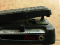
Is an interesting idea, most commercial amplifiers possess a footswitch to turn reverb, on or off, but with some modifications it is possible to operate the reverb volume pot, on the front panel of the amplifier, through a pedal, like the old wha-wha pedals.
Regards
Is an interesting idea, most commercial amplifiers possess a footswitch to turn reverb, on or off, but with some modifications it is possible to operate the reverb volume pot, on the front panel of the amplifier, through a pedal, like the old wha-wha pedals.
Regards
I don't play any instrument, but, I wonder if a foot peddle that is switch (at the top of travel) and rheostat (for max reverberation at bottom) is usable while playing?
Happy new year Andrew!
What you are describing is like a wah pedal. I'm not sure if it's desirable to vary the reverb effect like that. The original uses a front panel switch to turn the reverb on or this is overridden by plugging in a footpedal switch to the back panel jack. The front panel pots control the amount of reverb for each channel. This is basically how I will build it too.
Here is a chart of the overall build:

The line in / line out jacks can be used for an external effects pedal. The original has one 3 conductor jack for a 2 switch footswitch to control A/B channel selection and reverb on/off, but I have separated these, at least at the board level. They can be 2 individual 2 conductor jacks or 1 three conductor jack.
It's tricky to keep track of all of this but I have a better grip on it now. As I break up the original circuit into blocks, I gain a better understanding of how they work.
I was picking at the chorus section yesterday but I feel that it is hopelessly complex. This was the Gordian knot in my first attempt and I think I will replace the entire circuit with a less complex one that is supposed to have the same performance.
Last edited:
Hi AndrewT, happy new year
Is an interesting idea, most commercial amplifiers possess a footswitch to turn reverb on or off, but that alone, is an all or nothing situation.
With some minor modifications, it can control the level of reverb through a pedal like the ones used for wha-wha, with a pot inside.
Regards
Is an interesting idea, most commercial amplifiers possess a footswitch to turn reverb on or off, but that alone, is an all or nothing situation.
With some minor modifications, it can control the level of reverb through a pedal like the ones used for wha-wha, with a pot inside.
Regards
Attachments
Hi MJL21193, and happy new year
What kind of device is using in chorus circuit, a MN3007 perhaps?
Regards
Happy new year!
Yes, the MN3007 and clock gen MN3101. I have these and they test genuine so I will most likely stay with the original (after I get it sorted out) or go with another design, like the Boss CE-2.
I'm still working on the reverb and I have the layout nearly done. It is considerably smaller and less complex than either of the preamp boards. With 1 opamp and only 2 pots, getting it finished is much easier.
Hi MJL21193
About two years, build a guitar amplifier, where the circuit's chorus based in Marshall Valvestate 8080, is a complex circuit, particularly the section of the LFO, but the results surpass those obtained with the Boss CE-2, the BBD are one MN3007, and the clock section a MN3101, in the same amplifier, I put an echo circuit, based on 2 MN3005 working in series, try take a look at Marshall chorus circuit.
Regards
Try looking for Marshall 8080 Valvestate, chorus circuit,
Thanks for the suggestion
")
I looked but only found a schematic for the 8280. This is probably more work than I need at this time. After I have this amp done, I can look at other designs.
The advantage of the Boss CE-2 is that it is complete and self contained design, meant to work on it's own. I don't need to go to the trouble of picking it out of a larger circuit. Another advantage is it has a setup guide for the trimpot. This I don't have for the Ampeg. Not that it's a big deal but one less thing to puzzle through.
Reverb board is laid out:

ready to etch. It came out to be about half the size of the preamp boards at 10cm x 8.5cm. This time, I double checked the pinout on ALL of the transistors
As I'm out of good transfer paper ATM, I will be using the old standby - magazine paper. I don't have a critical top layer on this, where traces need to exactly line up so the mag paper will probably do ok.
This time, I double checked the pinout on ALL of the transistors
I should have triple checked.
One j176 with the drain and gate reversed this time. A couple of other minor mistakes and once they were fixed, I have a fully functional reverb:

It works exactly as it should and the level of reverb can be set independently for either channel

I ran the recorded guitar through it and it sounded great. I connected my function generator and wow, freaky sound effects! Manually sweeping the frequency up and down makes this wild eerie sound.
Anyway, it works. I need to fix the mistakes on the layout and make a new board but that can wait (at least until I have some decent transfer paper).
After some research, I've settled on the CE-2 chorus. It seems to be highly regarded and, aside from a few parts substitutions, it should be easy to build.
I have started to capture the schematic and I'm thinking that maybe it would be better to build this as a pedal. This would allow me to actually finish the amp build ( ) and do the chorus after.
So, with that plan in mind, I need to build one last board - to tie everything together, power supply for both the preamp section and the power amp. I start work on that today.
I have started to capture the schematic and I'm thinking that maybe it would be better to build this as a pedal. This would allow me to actually finish the amp build (
) and do the chorus after. So, with that plan in mind, I need to build one last board - to tie everything together, power supply for both the preamp section and the power amp. I start work on that today.
Last edited:
Power supply:

Pretty basic. I had a look through my stock of transformers and the most suitable one for the power amp is a 26.5-0-26.5. It is probably somewhere around 300VA, so it has enough oomph to drive the amp into a 4 ohm load.
The regulated 15V supply uses 4 regulators. I found that the preamps (with the support circuitry) are pulling enough current to heat up the single regulators. Probably overkill but I prefer to be safe and not have to do THIS over again.
The transformer for the 15V supply is a 12.6-0-12.6 @ 2A Radio Shack unit. I have 2 of these that have been kicking around for the past few years and haven't found a permanent use for. Again, a bit overkill but I use what I have.
I know this has been discussed here before, but looking at the quality of your work, you would have no problem making an actual tube amp. In fact, tube amps are much more forgiving in implementation of design than SS amps are.
The parts for tube amps do cost more though, so I don't know if that is a concern.
Just pick out a nice Fender or Marshall amp circuit to copy and try your hand at it...
Anyway, you do very nice work....
Good luck, Daniel
The parts for tube amps do cost more though, so I don't know if that is a concern.
Just pick out a nice Fender or Marshall amp circuit to copy and try your hand at it...
Anyway, you do very nice work....
Good luck, Daniel
Thank you Daniel!
Fortunately, I don't have any interest in tubes at this time. I feel it can be done just as well (or better) with solid state. If not, I'm sure I'll be happy with the results anyway, as long as I can get it working properly.
Also on the power supply board is the output buffer:

It combines the preamp signal and the reverb signal and adds some final gain before the power amp.
I have made the gain adjustable with a 100k trimpot and there is a few seconds before Q6 opens, via the RC made up of R2 and C14. This should give ample time for the power supply caps to charge up and the preamps and reverb to settle before there is any output. R3 drains C14 quickly when the power drops.
This should do it for the electronics. Next, after building and testing the power supply / output buffer, I'll need to do some metal work. A mounting bracket needs to be made to support the preamp and reverb boards. The whole lot can then be installed in the cabinet (!).
Fortunately, I don't have any interest in tubes at this time. I feel it can be done just as well (or better) with solid state. If not, I'm sure I'll be happy with the results anyway, as long as I can get it working properly.
Also on the power supply board is the output buffer:
It combines the preamp signal and the reverb signal and adds some final gain before the power amp.
I have made the gain adjustable with a 100k trimpot and there is a few seconds before Q6 opens, via the RC made up of R2 and C14. This should give ample time for the power supply caps to charge up and the preamps and reverb to settle before there is any output. R3 drains C14 quickly when the power drops.
This should do it for the electronics. Next, after building and testing the power supply / output buffer, I'll need to do some metal work. A mounting bracket needs to be made to support the preamp and reverb boards. The whole lot can then be installed in the cabinet (!).
I have the power supply/output board laid out:

Now, that is a comely looking board, if I do say so.
The final piece (fingers crossed, though there isn't much I could have mucked up on this one) and the rest is brute work.
I get this one etched tomorrow and see how badly I botched it.
Now, that is a comely looking board, if I do say so.
The final piece (fingers crossed, though there isn't much I could have mucked up on this one) and the rest is brute work.
I get this one etched tomorrow and see how badly I botched it.
I couldn't get to sleep last night so I made use of my insomnia to etch and stuff the power supply board:

Tests a-ok except one LM7815 is putting out more than 17V. I caulk this up to it being recycled from an earlier project. I'll pull and replace and see if that fixes the problem.
Everything else looks good. The output buffer works as it should, turning 'on' after about 3 seconds.
Nothing left to do now until I get the mounting bracket made. Then I can install the boards, the power supply, the power amp and wire it all up.
This project has been heavy on terminal blocks and I'm nearly out. Nice to have them on the boards for easy troubleshooting but I'm tempted to pull them and hard wire after I'm satisfied that everything is good.
Last edited:
I'm tempted to pull them and hard wire after I'm satisfied that everything is good.
I find them almost impossible to remove (non-destructively), especially when >2 pins.
Do you really think you will reach a point where you will stop tinkering/changing the amp?
I don't have any problem getting them out cleanly - most of the green ones in the preamp boards are recycled.
As for never stop tinkering - well, you know
I think I now have a good base for external expansion (if desired). The preamps are excellent and the reverb seems to be quite good. Getting the project all buttoned up, with a real guitar plugged in and in the hands of someone who can wield it (not me, yet) will be the final verdict.
- Status
- This old topic is closed. If you want to reopen this topic, contact a moderator using the "Report Post" button.
- Home
- Live Sound
- Instruments and Amps
- Guitar Amp Design / Build