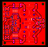
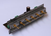
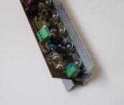
Just another idea for you. Done many times before, by many people, try it... you might be surprised.
http://bas.elitesecurity.org/leadstd.pdf
http://bas.elitesecurity.org/leadpro.pdf
Where were you yesterday..
I'm keeping all of the various design I've found and those will join them. Next time...
Not sure what pots you are using but should they not be flush with the edge of the PCB or even stick out a bit to allow the facepate to be mounted with ease?
Also I think you need mounting holes at the back, at the front there is already support from the pots.
I'm pretty good with metal so I'll make a mounting bracket where the pots are fastened and the board is fully supported. This assembly then gets screwed to the stainless steel faceplate. A picture (when it's done) will show what I mean.
As usualy on Sunday... Gone Fishing!
My loss!
Catch anything?
I have made the prototype board for the preamp:
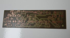
And the copper side:
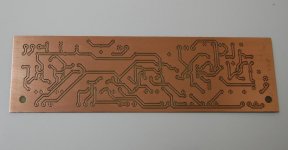
I'll need to drill it and then I can populate it with the parts I have. I'm waiting on pots and a few cap values.
I ordered the reverb tank - an Accutronics long delay, 3 spring mofo
More fun coming up.
More fun coming up...

Hi
how is it possible that you already etched the board?
your wife does not have works for you?
Yes, but he is doing his share of "hard works" every night and... if you follow his example, padamiecki, you will also have your boards done on time! Tra... Tra...Hi
how is it possible that you already etched the board?
your wife does not have works for you?
Hi
how is it possible that you already etched the board?
your wife does not have works for you?
No distractions to slow me down...
Hi , MJL . Did did you do this "action piece" with your HP printer ? I'm sold !!
Better and better , you will need to enlarge the house for more toys .
OS
Yes. I did have to do it twice though - I didn't clean the board well enough the first time. Check out the rez:
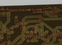
That's copper, fine as a hair.
I'm surrounded by my "babies" and more on the way...
you use your laser printer and then iron on the PCB? Is this how you do it?
Yes, it is fast and easy with some (ok, a LOT) of practice. I don't bother with perf board anymore, preferring to prototype this way - it allows me to see the things I need to fix for the final version. For example, I will increase the font size on the "silkscreen" to transfer cleaner and shift a few components around to make more space for others. Also, I see that my pads are still a little small.
John; I wanted to point out one thing: on your first schematic, in your first post, you've added an input buffer to Rob's design, and didn't move the 1-meg resistor over. Rob's design does have 1-meg input impedance.
Just an FYI.
You are absolutely correct.
That first schematic was put together quickly and I didn't look it over well enough before I posted it.
Hi MJL,
which laser printer and whose toner do you use.
have you had any toners that do not work as well.
My Brother toner cannot do this.
I am near to weeping.
Hi Andrew,
I have a Brother HL2030 laser printer and find this perfectly acceptable for PCB work, even for SM layouts. The secret is to find a suitable transfer paper! Having tried several different types, best results were obtained using a cheap inkjet glossy photo paper made by PCLine, though I don't know if this one is still available.
Regards,
Steve
Hi MJL,
which laser printer and whose toner do you use.
have you had any toners that do not work as well.
My Brother toner cannot do this.
I am near to weeping.
HP 3050 with genuine toner from HP. I haven't used any other toner.
Power supply for the guitar amp:
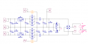
I have a 27-0-27 transformer, probably in the neighbourhood of 200VA that I'll use for this.
This gives ~35VDC for the power amp and preamp plus +/-12V regulated for the other "accessories".
The amp module will be one of my Patchwork amps that is sitting around, collecting dust. This is an excellent use for it.
Preamp is done:
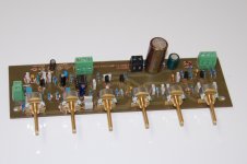
And tested:
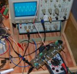
I had a couple problems - the first was a 47nF cap in place of a 470pF
The second was a good old fashioned solder bridge that I didn't spot the first 10 times looking.
Operates as it should, output is clean and undistorted. The tests are on my 30V lab supply so it's close enough to full power to evaluate it.
Of course, I don't have the reverb tank yet so I couldn't test that section.

And tested:

I had a couple problems - the first was a 47nF cap in place of a 470pF
The second was a good old fashioned solder bridge that I didn't spot the first 10 times looking.
Operates as it should, output is clean and undistorted. The tests are on my 30V lab supply so it's close enough to full power to evaluate it.
Of course, I don't have the reverb tank yet so I couldn't test that section.
One more thing you might like to try / add is the content of this article. Well, only if you want to make a "tube-ish" solid-state guitar amp, i suppose
Thanks Khron, that article is interesting and I will look at modifying the amp module to operate that way. The method looks fairly simple.
I have the power supply finished:
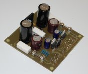
Works as expected but I did have to substitute 15V regs in place of 12V, I had some (supposedly from ST) that I used but the negative reg (7912) seems to have a different pin out. My board is laid out for the standard >GND<>IN<>OUT< for pins 1,2 and 3 but the one I used (and another that I replaced it with) MUST have a different pin pattern.
No matter now, I've switched both for 15V and all is well.
Here's the PS running my Abomination amp:
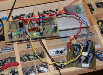
It's driving an 8 ohm dummy load and I'm seeing 19.2Vrms output just before clipping and the rail voltage is down to +/-32VDC. This translates into ~50 watts into 8 ohms and (further testing will reveal) nearly 100 watts into 4. That should be enough power.
Rain halted my metal work 
The next piece of business is the "harmonic multiplier" shown here from the G100A schematic:
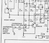
Any thoughts, opinions on this? I opted to follow the G50A which does not have this feature, thinking I will do an add on board and connect it in the same location in my preamp.
Is this the best approach? Are there better ways of doing this?
The next piece of business is the "harmonic multiplier" shown here from the G100A schematic:

Any thoughts, opinions on this? I opted to follow the G50A which does not have this feature, thinking I will do an add on board and connect it in the same location in my preamp.
Is this the best approach? Are there better ways of doing this?
- Status
- This old topic is closed. If you want to reopen this topic, contact a moderator using the "Report Post" button.
- Home
- Live Sound
- Instruments and Amps
- Guitar Amp Design / Build
