Andrew has a point. Kean, toss a coin whether the rail should be 60 or 80V and adjust the front end 10V up from that. Then decide if a shunt regulator is the way to go and we take it from there.
I think the most common secondary winding outputs are 40/45/50/55/60 Vac with DC around 56/63/70/77/84 Vdc.
I prefer lower voltage for the output. Anyone who wants to bias higher will have the option to do so.
And 9Vac (12.6 Vdc) extra winding (for the front end) is easy to find.
Attachments
Last edited:
Amusing table, or at least the last column is.
Hehehe
 Wish I can get away with that!
 Tanh, we all know your sims look good. But if you don't share, we can only ignore you!
- keantoken
I was wondering when someone was going to make a comment.
At this point in time I am not sure if I want to share the circuit. The main reasons for this are
1. I have not built it yet.
2. It might change the direction of the design. That is, it will be less like a Goldmund.
I will say this though. Never underestimate John Linsley Hood and overlook the posibility of tweaking the JLH version of this topology ie one less gain stage.
You can drive three pairs of laterals with this topology without issues.
Also consider dropping the rail voltages so that you can apply around 500mA to 1A bias current. For me I am happy to go up to 200W idle dissipation per channel, but I think most people will want to keep it under 100W idle dissipation per channel. +/- 60V DC might be a good compromeise.
I suppose I would like to see where you guys will take this design so that I can compare it to what I have. If I think what I have is better after comparing both versions then I will definitely share the circuit.
Hopefully I have given a few ideas that might improve the performance of this circuit. There are quite a few other things I have done differently (simpler), but I don't want to interfere to much here.
I want to learn as much as I can from this group effort without influencing it too much.
I think what we are aiming for is an output impedance below that of an electrolytic cap, and at least a comparable output inductance. As such your 1-Q reg needs gain. Salas' circuits are the perfect starting point.
- keantoken
Yes. Salas circuits are excellent.
Does anyone have a KNOWN good supplier of Devices?
Can anyone say that they have had a GOOD experiecnce with a Ebay seller for FETs that are HARD to get.
Can't we depend on how long someone has sold on Ebay and what his or her rating is?
It's not like we are blind and shooting in the dark.
Can anyone say that they have had a GOOD experiecnce with a Ebay seller for FETs that are HARD to get.
Can't we depend on how long someone has sold on Ebay and what his or her rating is?
It's not like we are blind and shooting in the dark.
What exactly do you want to buy?
If you are happy to use devices other than Hitachi, a group buy from Exicon will probably be the way to go.
Some people have even reported they prefer the exicon parts over the Renesas.
I can confirm the buz900 series are good, but have not heard Exicon or Renesas.
If you are happy to use devices other than Hitachi, a group buy from Exicon will probably be the way to go.
Some people have even reported they prefer the exicon parts over the Renesas.
I can confirm the buz900 series are good, but have not heard Exicon or Renesas.
My personal preference would be a Salas... With a degenerated BJT output. Will be faster and more predictable I think...
However I want it to be simple, too.
The criteria are:
Zout 20mohm or below
Very low output inductance
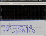
Is this one a lost cause? If I could eliminate C2/R7 without giving up output impedance...
- keantoken
However I want it to be simple, too.
The criteria are:
Zout 20mohm or below
Very low output inductance
Is this one a lost cause? If I could eliminate C2/R7 without giving up output impedance...
- keantoken
Attachments
At this point in time I am not sure if I want to share the circuit. The main reasons for this are
1. I have not built it yet.
2. It might change the direction of the design. That is, it will be less like a Goldmund.
I will say this though. Never underestimate John Linsley Hood and overlook the posibility of tweaking the JLH version of this topology ie one less gain stage.
You can drive three pairs of laterals with this topology without issues.
Also consider dropping the rail voltages so that you can apply around 500mA to 1A bias current. For me I am happy to go up to 200W idle dissipation per channel, but I think most people will want to keep it under 100W idle dissipation per channel. +/- 60V DC might be a good compromise.
When you implicitly said that the amp had a high efficiency, I thought it could be the JLH A/AB (or JLH 1982). I have built many JLH amps, also the GEM. Many others have based their work on the JLH, even the Aleph I believe.
I like JLH amps but not everyone do (especially the mosfet amps). Everyone has different priority! One of the circuit you have posted (on other thread) have single ended input to ensure H2 domination. Mooly's amplifier (60W) is a split supply design similar to that. Have you a high slew rate lateral amp? I'm afraid that your comparison will not be "apple to apple" (considering that you previously wanted to compare a Goldmund with an F5)
Last edited:
When you implicitly said that the amp had a high efficiency, I thought it could be the JLH A/AB. I have built many JLH amps, also the GEM. Many others have based their work on the JLH, even the Aleph I believe.
I like JLH amps but not everyone do (especially the mosfet amps). Everyone has different priority! One of the circuit you have posted have single ended input to ensure H2 domination. Mooly's amplifier (60W) is a split supply design similar to that. Have you a high slew rate lateral amp? I'm afraid that your comparison will not be "apple to apple" (considering that you previously wanted to compare a Goldmund with an F5)
You are thinking of the wrong amp.
JLH has designed many amps.
I posted the topolgy of it in the other thread, but no one seemed interested except from Salas (I think) who made a positive comment.
Yes it is high slew rate (if you go back in this thread you can see the performance) and yes it uses laterals.
Also I never said to use the JLH circuit. I said to modify it, just like we are doing to the Goldmund.
The only major difference in the topology between the JLH and Goldmund is the extra gain stage (ie beefed up driver stage)
Last edited:
Okay, I wanted try this on my own before asking advice.
If I had all the transistors I wanted I'm sure I could do this, but I want to keep it simple. Currently I've found no better option than to abuse a MOSFET as per the attachment. Does work though, with 20nH output inductance.
- keantoken
If I had all the transistors I wanted I'm sure I could do this, but I want to keep it simple. Currently I've found no better option than to abuse a MOSFET as per the attachment. Does work though, with 20nH output inductance.
- keantoken
Attachments
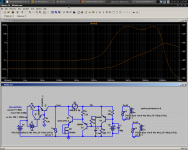
Okay, I wanted try this on my own before asking advice.
If I had all the transistors I wanted I'm sure I could do this, but I want to keep it simple. Currently I've found no better option than to abuse a MOSFET as per the attachment. Does work though, with 20nH output inductance.
- keantoken
Nice improvemennt. Keep going
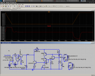
Kean,
here is a regulator that I use in my ELD amplifier, you can scale and modify it for whatever purpose you want. This one is meant for 10A, but change it for the purpose you need. I use microcap else I would have posted a schematic for your simulator and you could play immediately with it.
Nico
Man , this site is a goldmine. Differential based zener reg. , in a miniaturized form, I will have a sweet second set of rails for my voltage stages. Thank you, Nico.
OS
By Keentoken - In fact, the C-multiplier may be better, because if the rails sag for an extended period of time the C-multiplier will follow it rather than fight against it.
With a totally independent supply and a combined load for 2 channels of maybe a hundred mA ,you should not have much "rail sag" to contend with anyways. With my HV supply , I intend on going 120V DC +unregulated and regulating down to 100V rails. looking at nico's circuit , it seems to have voltage regulation and is part C-multiplier.
OS
- Home
- Amplifiers
- Solid State
- Goldmund Mods, Improvements, Stability