RAS ELD has been my Goldmund for more than 1 year but is now a commercial amp with a few changes. It does sound pretty handsome and it contains almost everything that has been mentioned in these threads. The commercial equipment contains a regulator on each channel as well as a few other refinements which I cannot show here, but what I show is a complete working machine in every-day use.
Some may not call it musical for what that statement means, but it is like water, it has no taste, no color, no flavor, no smell and, it gives what is inputted, no more no less. Some my prefer flavored drinks others fizzy drinks, etc, this amp does not do that, it is completely vanilla.
Maybe you could use some of the ideas from it. I have not been a fet input fan, I stick to BJTs, of course one change is front end that now uses 2SC2240 and 2SA970. I will post some sims below, not that they are of much use in practice, but gives an indication.
Shades of my CX2 , Nico. I see that this IS the same "rabbit hole" I will dive down in november. Now that I see this and the Ampslab Bi240 , I have renewed assurances.
") I am going to stick to the JFET/Cascode input stage this time , this topology is the first to get "blameless" type THD out of this arrangement .. at least in simulation.
I am going to stick to the JFET/Cascode input stage this time , this topology is the first to get "blameless" type THD out of this arrangement .. at least in simulation.By stating "vanilla" , I can see why . In isolation the VAS gave perfect -120 , -140 ,-160db distortion figures (H2/3/5-7 FFT). IN= OUT basically.
OS
Since you don't want to post and I keep secrets also, maybe a private post to compare notes. I love finding someone who can do better than me, I always benefit from it.
If mine is better than yours then it would most likely be due to luck, gut feeling, and trying to keep things simple as possible, as well as trial and error, forget about my knowledge of electronics. Maybe I underestimate myself here, but the more I know the more unanswered questions I seem to have.
As soon as I have tested this in the lab to confirm stability and performance, then I will be happy to share.
Hey, con someone tell me what kind of cap this is? I find them in radio receiver boards...
- keantoken
Murata 450 kHz ceramic resonator, not a capacitor.
Kean,
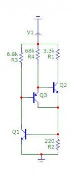
here is a high performance CCS you may want to consider. I used in RAS240. It may have the characteristics you are looking for.
Nico
Ah, the negative-impedance CCS... Homemodder showed me this before...
Did you know there is a way to tweak it for maximum output impedance?
Unfortunately, it is a super-powerful feedback loop, and instability might be an issue.
- keantoken
Murata 450 kHz ceramic resonator, not a capacitor.
I'm glad I didn't use it then! Funny thing is my tester measured at 450pF. Hmm.
Thanks,
- keantoken
OS
I said I had some sneaky mods. Kindly have a look at MAT03 from analog devices and use this in a cascode. You may change your mind.
MAT01 (npn) maybe , mine is "flipped around" from your ELD (BELOW-mostly N channel) , I will add your decoupling to my CCS. I have to use what I have a lot of (100 ea. 2sc3503 , 2sa1381, 2sc1845,2sa992) That mat is REAL low noise but I would have to cascode at 33v to just barely make my derating (45v for the mat /40 for the JFET = 75v rails). I really do get noiseless operation with the 1845/992's plus 120v Vceo - $.08USD apiece , buy a hundred and match them.
My ha ha "CX" "goldmund killer"( below) ($11.00 a channel
less total than a single MAT01 )OS
Attachments
Last edited:
Kean,
here is a regulator that I use in my ELD amplifier, you can scale and modify it for whatever purpose you want. This one is meant for 10A, but change it for the purpose you need. I use microcap else I would have posted a schematic for your simulator and you could play immediately with it.
Nico
Hi Nico, thanks for posting this. Is it possible to make double sided boards at home or do I need to get them professionally done? I would like to scale this to +/- 80V. Would changeing the Zeners and making sure cap ratings are fine be all I need to do?
Shouldn't the C5 filter cap by referenced to ground? This same error was in another schematic you posted here.
Also, try using NPN's for Q1 and Q2. Fed by a 100k resistor to ground. NPN's will have higher gain and hopefully be faster, and also have better loading than the 1k resistors. Or perhaps you've already tried this?
- keantoken
Also, try using NPN's for Q1 and Q2. Fed by a 100k resistor to ground. NPN's will have higher gain and hopefully be faster, and also have better loading than the 1k resistors. Or perhaps you've already tried this?
- keantoken
I use the regulator shown earlier. It works wonders compared to raw caps only.
What do you mean by "raw caps only"?
Did you compare:
(1) Using the regulator for both front stage and output stage
VERSUS
(2) Using "a" regulator to regulate front stage only?
I don't have experience on this so I have a suspicious feeling about using a regulator for the output. But of course it may depend on the type/quality of the regulator. And of course one needs to have a "good ear/mind" to listen to the subtle differences because there will always be good aspects from running any regulator for the output stage...
I guess/predict/believe that a good ear will be able to do this:
(1) Know that they sound different
(2) Know the positive AND the negative (soundwise)
(3) Know or can decide which one to prioritize (make correct decision)
I know that 10A regulator is expensive so you must have done the homework. I just want to make sure, and hope that anyone else would give their experience and explain their decision on the (3) above. Not all high end (cost no object) manufacturers/designers come to such decision after all.
Shouldn't the C5 filter cap by referenced to ground? This same error was in another schematic you posted here.
Also, try using NPN's for Q1 and Q2. Fed by a 100k resistor to ground. NPN's will have higher gain and hopefully be faster, and also have better loading than the 1k resistors. Or perhaps you've already tried this?
- keantoken
I did try that , as well as "flipping around" the circuit like in the ELD (nico's) , added nico's decoupling to ccs , added a CM to the "mix"... 'cool beans' ... even lower distortion. LG shot up to 100db+ at Low frequency. Sort of just what my goals were. I did change that zener bypass
. OS
Attachments
I like regulators for the front end stages only.
At the output I prefer just to use good old capacitor smoothing and plenty of it (within reason).
I also go with the biggest VA rated transformer I can afford. At a bare minimun twice the rated maximum power eg if it can do 400W into 4Ohms then I will use an 800VA transformer per channel as a bare minimum.
Why not invite Salas to make a recommendation?
You also want constant output impedance with respect to frequency.
Guys the simplest I can give you, is my SSHV with err... simplified CCS. Its been used from DHT preamps to phones amps by I don't know how many. It has very few components indeed. Keen maybe you can sim up the negative too in LT, since it comes from another simulator with not comparable features? Best thing is, look ma! No electrolytics! The Norton Vref is very silent for such an output level and adj. too. Sub a low ppm res after trim.
I enclose an LT Spice Analysis of the positive and a mirror example for negative, including the proper values for circa 100V out operation that should be migrated to the positive one too. Just put something in the rails, will help much, be it a good C mult. a shunt stabilizer (watch out the Vref element's physics & noise), or a shunt reg. This one needs 20mA left residual for 10mOhm Zo, hence my example is for circa 40mA total. Can go lower if running more, but the depletion has certain Idss limits too. Assuming you need 20mA for each rail, each IRF840 will dissipate 2W for 100V, and the depletion only Vin-Vout times 0.04A. 10V-20V drop is royal to keep it stable.
Attachments
I like regulators for the front end stages only.
At the output I prefer just to use good old capacitor smoothing and plenty of it (within reason).
I also go with the biggest VA rated transformer I can afford. At a bare minimun twice the rated maximum power eg if it can do 400W into 4Ohms then I will use an 800VA transformer per channel as a bare minimum.
Hi Thanh1973,
im curious about this, most people seem to dislike output stage regulation but I really want to try it on my next project, just to see. What did you not like about regulating the output stage?
Im all for front end regulation, it just seems to make sense.
- Home
- Amplifiers
- Solid State
- Goldmund Mods, Improvements, Stability