And what does it say when you do that? Does it list price and stock info? It doesn't. Krisf talked to the Arrow people and they said it's not on order and none in stock.According to there website, they sell them.
Type in 2sk216 in the part search
That they list a part on their site doesn't mean they have it.
There are a few sellers on ebay that have it but there is always the risk of fakes there.
Last edited:
hello.
.....has anybody a schematic of the psu of this amp?
greets
This is what I'm currently thinking about for the frontend. I imagine the power stage won't be actively filtered?
This is just a beefed up C-multiplier to me. There is no regulation involved, output follows the input voltage, even if very slowly due to the very high impedance feeding C1 and C2. Output impedance is comparable to low-ESR electrolytics.
- keantoken
Attachments
Okay, I had a post ready, but DIYAudio went through server maintenance and it went up in smoke.
Long story short, who is in favor of trying to preserve the sonics of the original, or do we want to morph it into something mostly different, but with really good specs? I will go either way.
- keantoken
Long story short, who is in favor of trying to preserve the sonics of the original, or do we want to morph it into something mostly different, but with really good specs? I will go either way.
- keantoken
Hi Keantoken,
why not just regulate the front-end properly instead of using "capacitance multiplier" Personally I would drop the voltage on the output to 65V per rail and run the front end at higher voltage to swing the mosfets closer to rails. Contrary to popular believe the output stage with gain less that 1 does not deteriorate THD, in fact it has little contribution at all. You need to reduce noise and distortion in earlier stages as much as you can.
Making a high voltage regulator is not that hard, besides you are assured of higher ripple rejection. Your capacitance multiplier uses almost as many components as a regulator in any way. As Andrew indicated the multiplier just adds a time constant it hardly improves matters.
Regulator
Kean,
here is a regulator that I use in my ELD amplifier, you can scale and modify it for whatever purpose you want. This one is meant for 10A, but change it for the purpose you need. I use microcap else I would have posted a schematic for your simulator and you could play immediately with it.
Nico
Kean,
here is a regulator that I use in my ELD amplifier, you can scale and modify it for whatever purpose you want. This one is meant for 10A, but change it for the purpose you need. I use microcap else I would have posted a schematic for your simulator and you could play immediately with it.
Nico
Attachments
Hello Nico. The PDF opens fine.
Using a regulator will give lower output impedance, but will most likely be slower. Some posters have told me they want a fast regulator, to complement the fast amplifier.
Further, my regulator has output impedance no lower than that of a low-ESR electrolytic. While this is large to some, it means it is relatively inert, and non-reactive. This may be important for high-speed designs where we must eliminate resonances which may be excited.
Thirdly, my design is a beefed up C-multiplier, but it is simple and trivial. The DIYer need not mess with it. It is not hard to troubleshoot.
As far as the differences between a regulator and a C-multiplier, I think the only difference is that one follows the output at DC and the other doesn't. If you think about it, both of them have to be designed so that an input voltage drop won't saturate the pass transistors. It is no different when my multiplier is set up to have a sub-Hz time constant. In fact, the C-multiplier may be better, because if the rails sag for an extended period of time the C-multiplier will follow it rather than fight against it.
This said, if you believe a lower impedance regulator will improve the sound, I trust you.
For this we have two options:
1: Series regulator not unlike what Nico has posted
2: Shunt regulator
The latter will have better output impedance and HF characteristics, and will give a natural protection against shorts and damage. A series regulator is not necessary I believe, since our frontend draws very little current (unless of course, we use FETs to drive BJTs and run them at 100mA).
So, my vote is for a simple, effective shunt regulator small enough to be put on the main PCB. However we will have to be more careful about decoupling and reactance.
- keantoken
Last edited:
Hi Hugh,
Long time no speak. Canadian amplifier manufacturer has kept me occupied almost 24hrs a day since three months ago. Will write you soon. BTW your buddy Rob seems like a pig that found a new mud puddle") )
)
Kean,
I have no problem with your suggestion at all. But in most electronics one want to keep voltage fluctuations out of the equation. I am not sure how one would defne speed in a capacitance multiplier, its job is to slow things down quite a tad.
Long time no speak. Canadian amplifier manufacturer has kept me occupied almost 24hrs a day since three months ago. Will write you soon. BTW your buddy Rob seems like a pig that found a new mud puddle
)Kean,
I have no problem with your suggestion at all. But in most electronics one want to keep voltage fluctuations out of the equation. I am not sure how one would defne speed in a capacitance multiplier, its job is to slow things down quite a tad.
this seems sensible.So, my vote is for a simple, effective shunt regulator small enough to be put on the main PCB.
But, I hope we aim for more than a resistor and Zener.
The use of 100R resistors on the gates of the mosfets seems very old school to me.You use the same gate resistor on the N and P channel FET.
Equivalant input capacitance on both complementary FETs?
Later lateral mosfet amplifiers that I have played with seem to use a higher value than this. 680R is one value that I have often seen used as a gate resistor. There is also the asymetrical capacitance of the lateral mosfet pairs, with the N channel 2sk1058 having an input capacitance of 600pF, and the P channel input capacitance being 900pF.
This can lead to oscillation as the N channel device is faster.
Solutions have included adding NPO/COG ceramics to the N channel gates, or using different value gate resistors for the N and P channel.
When reworking a lateral mosfet amplifier, my preferred gate resistors are 680R for the P channel and 1K for the N channel. If the low 100R resistance is preferable for this amp then maybe the N channel gate resistor should be increased to150R?
Piersma, I kept the original gate resistors used on the Goldmund. I don't know exactly how these should be set. It may have to be worked out on the prototype.
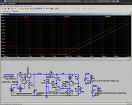
Nico, whenever I refer to speed in a regulator I mean effective output inductance. Every regulator/multiplier has reaction time. This tends to decrease with increasing active components. It's not much different from the ESL of a capacitor. For instance, you can see in the attachment that this regulator has a changing output inductance between 16 and 75 nH.
Andrew, it seems people want a lower impedance regulator, so hopefully we can get better than my C-multiplier without getting too complex. Attached is me playing with Salas-inspired circuitry.
- keantoken
Attachments
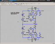
Nico, the upper rails supply is taken from the original Goldmund schematic. We are in the process of replacing it with the regulator we are discussing. The diodes form a voltage doubler.
Now that you mention it, many of the original transistors used weren't chosen for 120V rails, and it begins to make sense... 25mA through 2k is 50V, which leaves us with 70V. Output will be between 60 and 70V after the C-multiplier resistors factor in. I increased the driver bias, on the original it would be between 70 and 80V. Interesting!
So in fact the upper rails supply was actually carefully conceived. The increased rails help with filtering. For some reason Goldmund must have felt it important to filter the upper rails well.
- keantoken
Hi kean,
My vote is for a shunt and I would be using a transformer with multiple taps to derive the higher voltage for the regulator or a smaller transformer piggybacked on the main transformer to do the same.
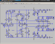
I think we should take the basic topology of the Goldmund an improve it and see where it ends, keeping with the spirit of the basic topology but not limiting ourselves to the type of devices used, type of outputstage used or circuit elements such as mirrors and current sources. I would like us to push to this to the max and see what we can come up with. Just my two cents.
Jam
My vote is for a shunt and I would be using a transformer with multiple taps to derive the higher voltage for the regulator or a smaller transformer piggybacked on the main transformer to do the same.
I think we should take the basic topology of the Goldmund an improve it and see where it ends, keeping with the spirit of the basic topology but not limiting ourselves to the type of devices used, type of outputstage used or circuit elements such as mirrors and current sources. I would like us to push to this to the max and see what we can come up with. Just my two cents.
Jam
- Home
- Amplifiers
- Solid State
- Goldmund Mods, Improvements, Stability