grufti said:This may well be a correct part with its matching picture:
http://www.mouser.com/Search/ProductDetail.aspx?qs=HLLy2pIPwusl7Ghj1oxxmA==
Please somebody correct me, if I am wrong.

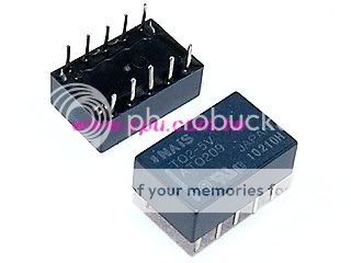
DS are bigger, xaudiox used these relay in his 1st version of the B1 deluxe than he moved into the more modern and compact TQ2.
Look at the pins: they don't match with the holes in the new pcb with pot.
Ds are always yellowish, while TQ are dark blue
see post #274grufti said:These relays are currently $2.76 at Mouser. How much cheaper can they get on eBay? I wonder where people source these for less.
If you buy surplus from a company that ordered 1 million pieces, you generally get them for pennies!
")
You can consider C15=47uF instead of 100uF. I have experienced adequate time delay with 47uF. Also try to listen with and without the 100nF capacitors you added on all electrolytics when you make the prototype. Sometimes they open the sound and sometimes they add harshness for numerous reasons.
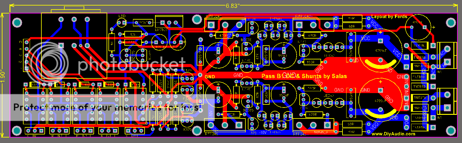
sorry again for another layout..
No, thank you for taking another shot at making it better.
I think once we went with 2 separate boards, ie basic and deluxe versions, there is no longer any need to keep the scoring.
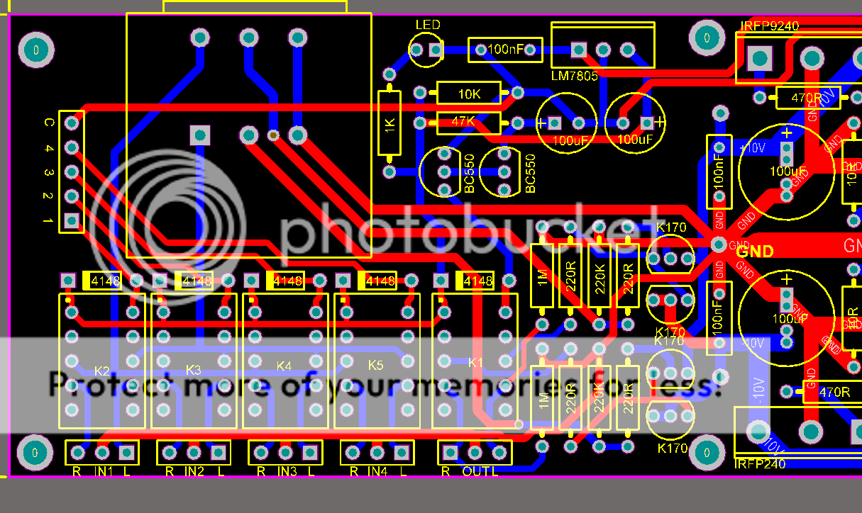
You layout looks great to me, but what would I know! One thing I would suggest, and only because its been real handy for me in the past is to organise the outputs so that you can use a 3 pin screw terminal or even 3 pin headers. Makes life very easy if you are moving something in and out a few times getting it running.
But either way is fine and I appreciate its getting tight on that board!
Thank you for so much effort in bringing this to us.
Fran


xaudiox said:i think the basic needs the scoring line since some members want the psu only..
++
i think the basic needs the scoring line since some members want the psu only..
++
- Home
- Group Buys
- GB for DC coupled B1 buffer with shunt PSUs