I'm unsure as the opamp circuit seems unnecessarily complicated. It even has 2 resistors connected in parallel to each other!This dac is too loud. Looking at the opamp circuit, it appears that increasing the 470R on both sides of the opamp will reduce the gain. Has anyone done this mod?
This dac is too loud. Looking at the opamp circuit, it appears that increasing the 470R on both sides of the opamp will reduce the gain. Has anyone done this mod?
Bernie,
If you change the resistors you'll change the gain but also the filter characteristics : cut frequency and Q factor. So you'll also have to change the capacitors.
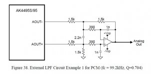
If the filter in our board is the one described in the AK4495 datasheet (see pic below) those characteristics may be calculated with the formulas found in the TI's application reports attached. See page 5, the differential filter is the same but with one of the two differential output grounded. This will allow to recalculate the rights caps after having changed the resistors.
If doing so, could you please share the description of the existing filter with the schematics and the value of the caps and resistors ?, I plan to change the gain, output level is too high.
Attachments
Aim65 yes you're right it's a LPF. The circuit used in the board does not resemble the example provided in the AK spec sheet from the resistor values it uses. It seems to follow some other opamp LPF design.
Also, do note that the RCA placement is rather unexpected - the one nearest the corner is L channel. I found this by tracing the circuit from the dac chip.
Also, do note that the RCA placement is rather unexpected - the one nearest the corner is L channel. I found this by tracing the circuit from the dac chip.
With the jumpers replacing the red switch, I've been able to change filters . I find Sharp rolloff, Short setting best for my room-equalised setup. In comparison Slow rolloff, Short Delay sounded a bit sharp and edgy.
From another thread, albeit an AK4490 DSD design, sonnya reported SSLOW sounds best, so we may not be missing anything in our fixed SSLOW mode.
http://www.diyaudio.com/forums/vendors-bazaar/274456-ak4490-usb-dac-dsd-support-27.html
From another thread, albeit an AK4490 DSD design, sonnya reported SSLOW sounds best, so we may not be missing anything in our fixed SSLOW mode.
http://www.diyaudio.com/forums/vendors-bazaar/274456-ak4490-usb-dac-dsd-support-27.html
Bernie,
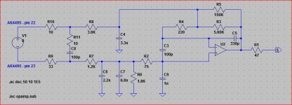
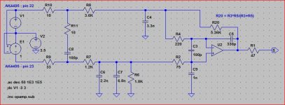
I've reconstruct the schematic of the Dac output stage, then loaded it into LTSpice. I then realized that it is the same output stage as the one described in the AKM application note (except for the 150k resistor) . As I do not have the formulae to calculate his behaviour, I'll do some trials with LTSpice to lower the gain and keep the frequency behaviour.
AKM application note may be found there : http://www.akm.com/akm/en/file/ev-board-manual/AK4495SEQ.pdf
Attachments
With the jumpers replacing the red switch, I've been able to change filters . I find Sharp rolloff, Short setting best for my room-equalised setup. In comparison Slow rolloff, Short Delay sounded a bit sharp and edgy.
From another thread, albeit an AK4490 DSD design, sonnya reported SSLOW sounds best, so we may not be missing anything in our fixed SSLOW mode.
http://www.diyaudio.com/forums/vendors-bazaar/274456-ak4490-usb-dac-dsd-support-27.html
Sonnya project is interesting. Regarding SSLOW and the digital filters I found a description within the marketing material of AKM, in section 'Key Features' of the Velvet Sound page : VELVET SOUND | AKM - Asahi Kasei Microdevices
Bernie,
I've reconstruct the schematic of the Dac output stage, then loaded it into LTSpice. I then realized that it is the same output stage as the one described in the AKM application note (except for the 150k resistor) . As I do not have the formulae to calculate his behaviour, I'll do some trials with LTSpice to lower the gain and keep the frequency behaviour.
AKM application note may be found there : http://www.akm.com/akm/en/file/ev-board-manual/AK4495SEQ.pdf
Good work! Look forward to your simulation data. Would be great if we know the present gain setting and if we can have a table showing component values corresponding to a reduction in gain of 3dB, 6dB etc down to unity gain.
I changed the two 47 Ohm output resistors to 470 Ohm on mine to reduce the gain.
dacster I believe the 47ohm resistors are there for cable loading. 470ohm may not give enough gain reduction for some and will reduce bandwidth of signal going to the amp by an order of magnitude.
Last edited:
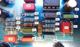
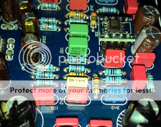
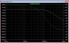
Aim65 is your board v1.0? Mine is v1.1 and its R02 is 470ohm, R08 is 3.5k as shown in the pic below. It appears that Weiliang changed at least R02 in ths revision, perhaps to adjust the gain. I haven't been able to spot other differences. I got my kit unsoldered and am sure the R02 position was labelled 470R.
Your R04, is it 220 or 330? I had mine at 330 it's hard to be sure with the color brown and orange, you might want to confirm before running spice. Strange to have 150k and 5.6k in parallel. Your data should give us some answers...
Your R04, is it 220 or 330? I had mine at 330 it's hard to be sure with the color brown and orange, you might want to confirm before running spice. Strange to have 150k and 5.6k in parallel. Your data should give us some answers...

Last edited:
After reading through many threads I have set my sights on building a DAC based on the AK4495. Looking at numerous boards from ebay I am a bit lost on what to pick. I will be using optical input, but it would be nice to use USB down the road.
The last DAC I put together was the AMB y2 few years back, so I'm not up to date on current hardware.
Am I right in saying using USB input and DSD will require drivers, but using optical would function as per normal (volume control through windows).
Some of my Audio gear has balanced XLR inputs, are there any boards currently that offer this output?
Many thanks, sorry for all the questions!
I get theses on an ebay page, I think it may help :
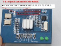
USB-DM" connect to " D- " of the USB; "USB-DP" connect to " D+ " of the USB; VBUS is also connect to usb
>>7 pins: 1 (VBUSE); 2(USB-DM) ; 3(USB-DP) ; 4 ; 5(S1) ; 6(GND) ; 7(S1A)
S1 and S1A are coax Spdif out
USB-DM" connect to " D- " of the USB; "USB-DP" connect to " D+ " of the USB; VBUS is also connect to usb
>>7 pins: 1 (VBUSE); 2(USB-DM) ; 3(USB-DP) ; 4 ; 5(S1) ; 6(GND) ; 7(S1A)
S1 and S1A are coax Spdif out
Attachments
After my post #70 I've done some research and I'm now pretty sure our board won't run dsd whatever Xmos or equivalent board installed. Modifying the board for // mode will require to unsolder many pin of the 4495, connect (by wire) them to a microcontroller with 3.3v I/O then write the software. It would be much better to also remove the current 8051 controller and also take control of the 4118 and the LCD display, and also to add a remote control, etc... It will be easier and certainly safer to build a new one from scratch or from a simple board from DIYHK (the AK4490 one).
Bernie, my board is 1.1 and I confirm R2 is 75 Ohm, R8 is 3.6k and R4 is 220 Ohm. I think the 150k is aimed at fine tuning the gain and filter.Aim65 is your board v1.0? Mine is v1.1 and its R02 is 470ohm, R08 is 3.5k as shown in the pic below. It appears that Weiliang changed at least R02 in ths revision, perhaps to adjust the gain. I haven't been able to spot other differences. I got my kit unsoldered and am sure the R02 position was labelled 470R.
Your R04, is it 220 or 330? I had mine at 330 it's hard to be sure with the color brown and orange, you might want to confirm before running spice. Strange to have 150k and 5.6k in parallel. Your data should give us some answers...
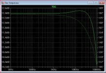
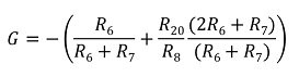
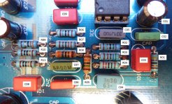
The gain is the pic attached, it should be correct but it's a very long time I haven't made those kinds of calculation
") ..... Notice that R20=R3//R5
..... Notice that R20=R3//R5On my board it's near +3dB. Cut frequency is around 105kHz.
I've fixed an error in the layout and changed the diagram in order to get it closest to the output stage of the DAC. (differential with DC offset)
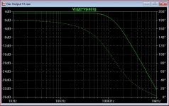
Please also fin a plot with your values of R2, R8 and R4 : bernieplot.jpg
Attachments
- Status
- This old topic is closed. If you want to reopen this topic, contact a moderator using the "Report Post" button.
- Home
- Source & Line
- Digital Line Level
- Finally Weiliang released ak4495+ak4118 dac today.