Thank you AIM65,
The Assembled AK4495SEQ AK4118 NE5534 Double Parallel Soft Control Board DOP DSD | eBay looks interesting.
Look forward to feedback about selecting a AK4495 or AK4495SEQ
All the best
If you only plan to use the DAC in I2S provided by the Raspberry it could be easier to move to simpler boards such as :
768kHz/32Bit AK4490EQ DAC, I2S/DSD input - DIYINHK or
768kHz/32Bit AK4495SEQ DAC, I2S/DSD input - DIYINHK
but if the quality of the the I2S output (jiiter) of the Raspberry isn't that good, it certainly better to output an SPDIF signal that will be I2S transformed by the AK4418 used on the boards of our previous mail, assuming it has better clock characteristics than the Raspberry. 4490, 95 and 97 require MCK and LRCK to be provided externally, which seems not to be be the same for all dac chips.You may find some threads on the forum about this issue of Raspberry I2S clocking and jiiter.
Regards
Selecting a single or dual AK4495 or AK4495SEQ DAC
Dear AIM65,
Thank you for the suggestion. Found one thread on Raspberry Pi clocking and jitter, there does seem to limitations to I2S.
It seems the AK4495SEQ is very good at "increasing performance for
systems with excessive clock jitter." Maybe the 768kHz/32Bit AK4495SEQ DAC, I2S/DSD input - DIYINHK is all I would need.
Anyone else have a suggestion ? Thank you!
If you only plan to use the DAC in I2S provided by the Raspberry it could be easier to move to simpler boards such as :
768kHz/32Bit AK4490EQ DAC, I2S/DSD input - DIYINHK or
768kHz/32Bit AK4495SEQ DAC, I2S/DSD input - DIYINHK
but if the quality of the the I2S output (jiiter) of the Raspberry isn't that good, it certainly better to output an SPDIF signal that will be I2S transformed by the AK4418 used on the boards of our previous mail, assuming it has better clock characteristics than the Raspberry. 4490, 95 and 97 require MCK and LRCK to be provided externally, which seems not to be be the same for all dac chips.You may find some threads on the forum about this issue of Raspberry I2S clocking and jiiter.
Regards
Dear AIM65,
Thank you for the suggestion. Found one thread on Raspberry Pi clocking and jitter, there does seem to limitations to I2S.
It seems the AK4495SEQ is very good at "increasing performance for
systems with excessive clock jitter." Maybe the 768kHz/32Bit AK4495SEQ DAC, I2S/DSD input - DIYINHK is all I would need.
Anyone else have a suggestion ? Thank you!
Do any or all of these cards offer spdif input facility? [Info seems limited on eBay and last card I bought needed solder link to make it accept my CD transport. [I am not intending going down the computer storage route].
Those three ones : NO
768kHz/32Bit AK4490EQ DAC, I2S/DSD input - DIYINHK
768kHz/32Bit AK4495SEQ DAC, I2S/DSD input - DIYINHK
Top Grade AK4495SEQ DAC Assembled Board I2S to RCA Upgrade Your Player Weiliang | eBay
Those two ones : YES
Assembled AK4495SEQ AK4118 NE5534 Double Parallel Soft Control Board DOP DSD | eBay
New AK4495 AK4118 DAC Decode LM49860 High Quality Assembled Board for Weiliang | eBay
Cheers
Those three ones : NO
768kHz/32Bit AK4490EQ DAC, I2S/DSD input - DIYINHK
768kHz/32Bit AK4495SEQ DAC, I2S/DSD input - DIYINHK
Top Grade AK4495SEQ DAC Assembled Board I2S to RCA Upgrade Your Player Weiliang | eBay
Those two ones : YES
Assembled AK4495SEQ AK4118 NE5534 Double Parallel Soft Control Board DOP DSD | eBay
www.ebay.com/itm/NEW-AK4495-AK4118-DAC-Decode-LM49860-High-quality-assembled-board-for-weiliang-/141491847769?afsrc=1&rmvSB=true]New AK4495 AK4118 DAC Decode LM49860 High Quality Assembled Board for Weiliang | eBay
[/COLOR]
Cheers
@AIM68:
Many thanks for your advice....I know little about DACs so you advice is very helpful...thank you.
I have looked at the last two which you say have spdif capability. Of these the first seems to be the one with dil switches which I read have been trouble...so for safety I will order the second one (highlighted in blue in the quote.
Dear AIM65,
Thank you for the suggestion. Found one thread on Raspberry Pi clocking and jitter, there does seem to limitations to I2S.
It seems the AK4495SEQ is very good at "increasing performance for
systems with excessive clock jitter." Maybe the 768kHz/32Bit AK4495SEQ DAC, I2S/DSD input - DIYINHK is all I would need.
Anyone else have a suggestion ? Thank you!
Museguy,
I've no experience with RPI, but I know AKM's Dac require a master clock linked to the sampling frequency (not a constant one if you want to change the sampling frequency). This Master Clock is key for the jitter noise and sound quality because it drive the internal delta-sigma converter within the chip.I don't know if RPi is able to provide such one.
This link may provide you some answsers :https://hifiduino.wordpress.com/2014/11/13/raspberry-pi-b-digital-audio/
Dear AIM65,
Thank you for the suggestion. I have asked the question at hifiduino
"Is it better to use a Digi + board or I2S input ?
DGI+ coaxial in to a Dual AK4395SEQ Assembled AK4495SEQ AK4118 NE5534 Double Parallel Soft Control Board DOP DSD | eBay
Or something like the AK4395 I2S 768kHz/32Bit AK4495SEQ DAC, I2S/DSD input - DIYINHK
Can the RPi supply a master clock linked to the sampling frequency ?"
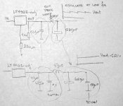
How to solve oscillating on LT1963-adj. I had a inductor and put between small cap after LT, and big 680uF capacitor. Maybe 10r resistor works fine on the same place, i did not try.
Would be much easier to add an 1ohm resistor in series with the 0.1uF. The low ESR 0.1uF is making the chip oscillate, and for the purpose of lowering the HF output impedance, 1ohm doesn't really matter.
How to solve oscillating on LT1963-adj. I had a inductor and put between small cap after LT, and big 680uF capacitor. Maybe 10r resistor works fine on the same place, i did not try.
Is there any input cap? I didn't see it on your diagram.
Problem is not in input capacitor. Capacitor after LT is to big and LT can not regulate output voltage. I have put small cap on output LT and small inductor between those caps.
After that mod i love this detailed and relaxes sound
After that mod i love this detailed and relaxes sound
Attachments
Hi
My transformer blew on this model. Looking for some help on the specifications
what i have
Input (Primary) - 0-115-230v
Output 1 - 15-0-15v - require the output power in amps/milliamps here
Output 2 - 0-9v - again require the output power in amps/milliamps
Output 3 - 0-9v - require the output power in amps/milliamps
total power 30VA.
50-60hz
Last edited:
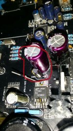
Mod akm4495
Would you show me in detail how to mod this board?Skrstic,
Mods are identified by yellow arrows in the two pictures.
On Above view :
• Restored control over SD and SLOW filter select switches : changed misplaced Dip Switch by jumpers
• Installed resistor attenuator on the output in order to reduce output level (-9,5dB)
• Changed 220uF on VDDL/R and VRefL/R on the output of the 6,7V regulator (LT1963) by 1500uF
• Removed film cap for high frequency decoupling of OpAmp
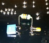
On Underneath view :
• Turned Off SSLOW filter :
o cut DVDD (+3,3V for Digital domain) track before and after the via feeding pin5 of the 4495.• Resistor attenuator
o Connected the via to ground.
o Reestablished the connection to DVDD (brown wire)
• installed OpAmp decoupling as closest as possible to the chip and with rights caps
• Installed discharge resistor for the 1500uF cap (see above)
That’s it, the DAC sounds OK for now. Next mods are planned in order to replace the MCU by an Arduino and take full control of the AK4495 and 4118. I also have to find a way to check if some critical component (LT1963, Oscon Cap on the Xmos board, 22uF cap around the 4495,…) are not fake.
- Status
- This old topic is closed. If you want to reopen this topic, contact a moderator using the "Report Post" button.
- Home
- Source & Line
- Digital Line Level
- Finally Weiliang released ak4495+ak4118 dac today.