The slightly soft room-temperature elasticity of hot-melt glue should actually help decrease any coupled mechanical noise of the fan to the plinth.
It should work great! -- however it looks like the black mesh can be removed by itself to leave the black metal(plastic) in place, where the screws attach to the wood. At least that's what it looks like from the photos. Can you pry it off and have everything else intact? Or will the mesh unscrew, and then you can screw the mount and fan back together?
It should work great! -- however it looks like the black mesh can be removed by itself to leave the black metal(plastic) in place, where the screws attach to the wood. At least that's what it looks like from the photos. Can you pry it off and have everything else intact? Or will the mesh unscrew, and then you can screw the mount and fan back together?
Last edited:
i have been thinking of building some stands like this myself. but instead of 1 senter mounted fan, i was thinking of multiple smaller fans along the side edges. and use a temp sensor on the sinks inside the amps with a smal PSU and a Jack conection on the back of the amps. so it only runs on realy hot days. wich we have had alot of this summer")
thats what i'm thinking
More fans, more noise, though.
Painted it flat black so to not bring much attention to it.
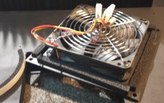
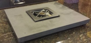
I removed the screen and then used foam weather stripping between the fan and stand. I tightened the mounting screws just enough to keep good tension on the foam. It ran so quiet I did not use any hot glue.
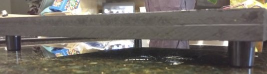
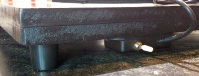
Mounted 7/8 inch feet to the base. I'll add a small enclosure for connections and a switch in a couple days.
Sorry for some of the out-of-focus shots. I think the camera had problems with the shiny granite counter. You can see the reflection of the bottom of the fan on the counter-top in the last photo.
I removed the screen and then used foam weather stripping between the fan and stand. I tightened the mounting screws just enough to keep good tension on the foam. It ran so quiet I did not use any hot glue.
Mounted 7/8 inch feet to the base. I'll add a small enclosure for connections and a switch in a couple days.
Sorry for some of the out-of-focus shots. I think the camera had problems with the shiny granite counter. You can see the reflection of the bottom of the fan on the counter-top in the last photo.
Attachments
I guess the fan "base" is one way to go.
However, NP published, and others have done much the same, a simple circuit that uses a 3pin adjustable vreg chip and a temp sensing element (thermistor, or other) as a control element to adjust the voltage out of the vreg chip. The vreg chip controls a DC fan. There is a "low side" adjust pot so that the fan can be set for minimum rotation at quiescent (low noise) and only increase in RPM if heat increases.
I'd go for it.
The other thing is you might do well to put some foam front and back that contacts the chassis, and then something short and vertical along the two sides that go to the heatsinks. In this way the air is routed up and across the heatsink surface. The greater the efficiency, the lower the fan speed required (if any) and the lower the noise.
the voltage regulator for speed control is not that critical when the fan(s) are sitting in free air, as it is when they are mounted in a chassis. but on the the other side. they dont hurt eighter most of the fan noise one normaly hear is acctualy mecanical resonance from chassis.
most of the fan noise one normaly hear is acctualy mecanical resonance from chassis.Sometimes I am dumb, and then sometimes I am extraordinarily stupid. Today is the latter case.
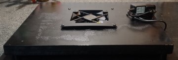
I have attached a couple photos of the cooling stand, now with a nice power switch and another coat of paint. I placed the amplifier on the stand, and it fit perfectly.
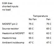
To examine the effectiveness of the fan, which cannot even be heard at five feet from the amp, I let the amplifier sit for two hours biased at 0.8 A, inputs shorted, and no load on speakers. I confirmed offsets of < 3 mV. That is, I let the amp warm up for about two hours and slightly readjusted bias, and then let it sit another two hours, during which time the bias and offsets did not change.
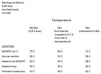
Then, I took temperature measurements on pin 2 of the MOSFET, on source resistors, top of the heat sink, on the heat sink in proximity to the MOSFET, and in ambient air within the sealed amplifier.
Then, I turned on the fan and let the amplifier sit another two hours and repeated measurements. I was quite surprised by the results, which are summarized in the third photo.
Hmmm. Not a single change. I once again made sure the fan was on. And, of course, confirmed it was blowing air up rather than down.
I then took a look at the top panel of the chassis and realized that the bottom panel directly over the fan was identical. See any problems?
I have attached a couple photos of the cooling stand, now with a nice power switch and another coat of paint. I placed the amplifier on the stand, and it fit perfectly.
To examine the effectiveness of the fan, which cannot even be heard at five feet from the amp, I let the amplifier sit for two hours biased at 0.8 A, inputs shorted, and no load on speakers. I confirmed offsets of < 3 mV. That is, I let the amp warm up for about two hours and slightly readjusted bias, and then let it sit another two hours, during which time the bias and offsets did not change.
Then, I took temperature measurements on pin 2 of the MOSFET, on source resistors, top of the heat sink, on the heat sink in proximity to the MOSFET, and in ambient air within the sealed amplifier.
Then, I turned on the fan and let the amplifier sit another two hours and repeated measurements. I was quite surprised by the results, which are summarized in the third photo.
Hmmm. Not a single change. I once again made sure the fan was on. And, of course, confirmed it was blowing air up rather than down.
I then took a look at the top panel of the chassis and realized that the bottom panel directly over the fan was identical. See any problems?
Attachments
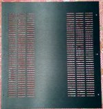
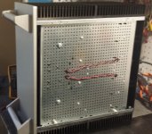
I set the amp on its side and removed the feet and bottom panel and grabbed a photo to show how the bottom panel's central, solid portion prevented air movement into the amplifier, since it was directly over the fan.
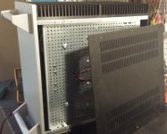
I left the bottom panel off (second photo) and then remounted the feet and set the amp back on the stand, turned things back on and let it cook with the fan running.
After about 2 hours, I took measurements again (3rd photo). Temperatures were dramatically lower, and I could feel air moving out of the ventilation holes on top of the amp. BUT, the lower temperatures were accompanied by lower bias - it had dropped from 0.8 A to 0.7 A. Of course, a MOSFET's output increase with temperature (which is why there are thermistors in the F5 to decrease Vgs as temps rise), and my primary effort to lower temperature also lowered MOSFET output, which in turn, lowered temperature, until a new equilibrium was reached.
At least in my case, then, if I would have biased without a fan to 0.8A, noted what temperatures were, and then found that temps became lower with a fan running, this would have been, in part, because of decreased output from the MOSFETs that I would not have recognized.
In order to compared oranges to oranges, I re-biased the amp to 0.8A with the fan in operation and let the amp cook again for a couple hours and repeated temperature measurements after confirming bias had remained at 0.8 A. As seen in the 3rd photo, temp measurements were, indeed, lower than biased at 0.8 A without a fan, exactly in the range that Zen said they would be (about 5 C lower).
Now, I can drill holes in the center of the bottom panel, directly over the fan, to allow air into the amplifier (and won't get as much air flow as I do now), or I can build a new stand with two smaller fans on each side of the bottom panel where there are ventilation holes....or two smaller fans just over the heat sinks....or 4 fans..... For now, I'm going to drill some holes in the center and see what I can get.
Attachments
...... or I can build a new stand with two smaller fans on each side of the bottom panel where there are ventilation holes....or two smaller fans just over the heat sinks....or 4 fans..... For now, I'm going to drill some holes in the center and see what I can get.
do not drill amp case
make new babysitter base , with one 12cm vent per side (no smaller) , bias amp to 0A8 without fan and enjoy
when you feel 55C - turn fans on , when you feel colder amp (colder days) , don't power them
that's not nuclear science
- Status
- This old topic is closed. If you want to reopen this topic, contact a moderator using the "Report Post" button.
- Home
- Amplifiers
- Pass Labs
- F5c (cascode) cviller boards 40 V rails build