Heh, after the above comment I actually looked at the pix of the boards... seems odd to me, IF the blue box cap at the first right side mosfet is what you added?? What's the pinout on those mosfets anyhow, perhaps that is between the drain and the gate??
Where did NP say to put these caps??
I would have expected some smaller cap(s) between the drain and gate myself... in the 10s of pf range...
...the idea that this "worked" bears some more investigation, imo, if that's not the drain and gate. .
Where did NP say to put these caps??
I would have expected some smaller cap(s) between the drain and gate myself... in the 10s of pf range...
...the idea that this "worked" bears some more investigation, imo, if that's not the drain and gate. .
Papa puts it between gate driver (before gatestopper) and output, which shunts oscillation to output.
The toxic approach appears to be putting a capacitor in series with the internal gate capacitance and thus decreasing the capacitance from a oscillation perspective and thus pushing it up higher in frequency... but yes we need to think about this one.
The toxic approach appears to be putting a capacitor in series with the internal gate capacitance and thus decreasing the capacitance from a oscillation perspective and thus pushing it up higher in frequency... but yes we need to think about this one.
Hi Christian,
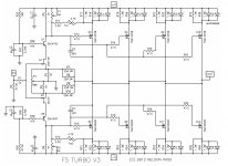
The cap runs from just before the gatestopper to the drain (center lead, output) of the MOSFET. The angle of the closeup of the cap doesn't show this clearly in the low-resolution photo I posted. That is, the cap on a given board is placed on the N-channel devices at the location shown for C4 on the version 3 schematic (attached).
Andrew, I have an analog scope, but it is heavy enough that i didn't want to drag it a few hundred miles through airports.
But I think I can get the P-channel caps in place in the next few days, though I won't be able to haul my scopes and signal generator. In a few weeks I may be able to study the amp in more detail again.
Attachments
Last update (I hope).
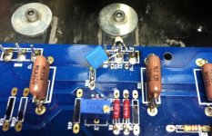
Got a 1 nF cap installed on the P-channel side of each board (example photo attached). So now each board has a cap from drain to just before the MOSFET gatestopper on a single N-channel MOSFET and a single P-channel MOSFET.
The amplifier sounds wonderful.
Next time I wander to the fine city where this amplifier resides and am taking luggage, I'll see if I can drag my analog scope, but will at least take my digital scope and signal generator and add some lower value caps in parallel to see if we can correct that final minimal overshoot, as suggested by Bear. Or I might increase the size of gatestoppers. We'll see and I'll report back then.
Thanks, everyone, for your expert advise.
Attachments
A while ago, I ordered a small batch of those boards that toxic ingestion have discussed in this thread. I was lucky enough to be able to add the capacitors before I sent the file for production, so I have named the version F5c V2.2. Otherwise, the board is identical to the one described in this thread.
To keep things organised, I have placed in on my simple order site:
F5c V2.2 (cascode-able)
It connects to paypal, but I have not used the site for a few years, so please email me if you run into issues. And also email me if you have questions - I have turned off PM because I forget to go in and reply to PM messages.
Cascode resistors question
Hi,
I've had the Stores' F5 V2.0 by CViller boards
on my to build list since February 2012 .
Finally getting around to building them up.
Have soldered in all resistors save for those
in the feedback and the cascode portions.
I see there are variations on values for these
two areas.
One has 10k0R for R101;2;3;4 and adds a
gate resistor of 475R.
Another has 4700R for R101;2;3;4 and
no gate resistor on Q101;2.
Their may have been another but I
can't find it.
The feedback values I've seen are
two 100R and two 220R, giving
50R or 110R for feedback.
Please help me choose, so I can
finally complete this amp.
The cascode resistor choices are my main concern.
Thanks,
Hi,
I've had the Stores' F5 V2.0 by CViller boards
on my to build list since February 2012
.Finally getting around to building them up.
Have soldered in all resistors save for those
in the feedback and the cascode portions.
I see there are variations on values for these
two areas.
One has 10k0R for R101;2;3;4 and adds a
gate resistor of 475R.
Another has 4700R for R101;2;3;4 and
no gate resistor on Q101;2.
Their may have been another but I
can't find it.
The feedback values I've seen are
two 100R and two 220R, giving
50R or 110R for feedback.
Please help me choose, so I can
finally complete this amp.
The cascode resistor choices are my main concern.
Thanks,
Cascode -
It doesn't actually matter much, as the resistors are making a voltage divider that sets the cascode transistors at 1/2 the rail voltage. As long as the resistors as the same value, it will do the job. Use 4700ohm if you need a decision made. But 10k will work just as well.
Gatestopper -
Yes, use them. 100-470ohm, whatever you have in your pile of parts on hand.
Feedback -
More ohms will give more gain and less feedback. The F5 uses (4) 100ohm, the F5T uses (4) 220ohm. It really depends on if you need the gain or not.
Cascode -
Use 4700ohm if you need a decision made.
Gatestopper -
Yes, use them. 100-470ohm, whatever you have in your pile of parts on hand.
Feedback -
More ohms will give more gain and less feedback. The F5 uses (4) 100ohm, the F5T uses (4) 220ohm. It really depends on if you need the gain or not.
Thank you for the reply
ps By gate stoppers, are you reffering to the output mosfets or input jfets?
Actually I was reffering to the cascode bipolar transistors, where
toxic ingestion http://www.diyaudio.com/forums/pass-labs/229434-f5c-v2-0-cascode-build-documentation.html shows a 475R resistor on the base inputs.
I posted gate but meant base.
I have & will use 4k7R for cascode.
I will use 50R caddock power resistors for each branch of the feedback.
In the original F5 I have I used two 100Rs (50R) and it had sufficient
gain for my speakers.
-ICHI
Last edited:
If the Caddock are 6-10W, use them!
Don't forget the gatestoppers.
Yes, I use gate stoppers on jfets and mosfets, always.
But, what about the resistor on the cascode bi-polars?
jfet & mosfet questions
Hi,
For the input jfets what idss should I shoot for?
I have 7;8;9;&10s I think.
Thinking a higher idss would be needed to
drive the extra set of outputs.
For the outputs, I have
FQA12P20 & 19N20c Fairchild I believe matched;
12P20 & 16N25c Fairchild (octtets are matched) ;
2SJ618 & 2SK3497 Toshibas (quads matched) .
Which of these would make a sweet amp output?
ps: CVillar, thank you.
If you read the F5T article the decrease in feedback and corresponding increase is gain is for stability, not necessarily just to increase gain. It lowers feedback and bandwidth.
http://www.firstwatt.com/pdf/art_f5_turbo.pdf
As for the mosfets, I have used IRF, Fairchild and Toshibas. I like the Toshibas best but mine are 2SK1530/201. If you want a warmer sound I would probably use IRFs. The fairchilds were the "hardest" and most clean.
http://www.firstwatt.com/pdf/art_f5_turbo.pdf
As for the mosfets, I have used IRF, Fairchild and Toshibas. I like the Toshibas best but mine are 2SK1530/201. If you want a warmer sound I would probably use IRFs. The fairchilds were the "hardest" and most clean.
Thanks 6L6 and Hikari1 and CVIllar!
I will have to mod the pcbs in order to mount
resistors for base stoppers on the cascode bi-polars.
I will add a small cap across the feedback resistor
if needed for stability. My scopes been dead about
20 years, so I'd have to rely on a loss of high frequency
content to indicate oscillation?!
I will use the 8 or 9 idss jfets for input,
and Tosh J618 &K3497's for outputs.
I will use my displaced original CVillar F5
boards to power Hitachi J50 & K135 outputs.
Last edited:
This amplifier was run very hard for about 2.5 years, never turned off. When a new preamp was hooked up and turned to maximal output, the amp blew a channel. Given that there was still a very slight overshoot on the square wave, even after the 1 nF caps were i place on N and P channel devices on both boards, I suspect it oscillated once again. (But I need to look at the new preamp to see whether there were coupling caps to output, or whether there was any possibility of DC on the outputs.
I have just constructed new boards, but increased the gate-stoppers on the MSOFETs to 100 ohms. I also installed the 1 nF caps. Still, there was slight overshoot on the square wave. I experimented around and found that 100 ohm gate stoppers AND 33 nF capacitors were ideal. The square wave was just rounded near the top and bottom. Looked beautiful. This is what I'm using now.
Steve
Phoenix
- Status
- This old topic is closed. If you want to reopen this topic, contact a moderator using the "Report Post" button.
- Home
- Amplifiers
- Pass Labs
- F5c (cascode) cviller boards 40 V rails build