Nice build") Only one concern. What is your bias goal?
Only one concern. What is your bias goal?
This will be around 85W @8ohm amp (voltagewise). If you want it to stay in class A all the way, you wil need 1.15A pr device with 2 pairs. With +/-40V rails, that comes to 46W dissipation pr device. and a total of 184W pr ch. that might make the amp a little to hot. and the Lifetime of the outputs a little to short.
Only one concern. What is your bias goal?This will be around 85W @8ohm amp (voltagewise). If you want it to stay in class A all the way, you wil need 1.15A pr device with 2 pairs. With +/-40V rails, that comes to 46W dissipation pr device. and a total of 184W pr ch. that might make the amp a little to hot. and the Lifetime of the outputs a little to short.
Hi. I don't understand exactly what you mean by your statement that you mount "them upside down (with mosfets in the bottom)." Might you explain a bit or provide a quick photo or sketch?
Thanks.
I think Zen Mod said it pretty well. So, if you have mosfets on one side of the board and mount the board parallel to the heatsink, you can choose to turn around the board to have the mosfets below or above the board. Below is better.
I think Zen Mod said it pretty well. So, if you have mosfets on one side of the board and mount the board parallel to the heatsink, you can choose to turn around the board to have the mosfets below or above the board. Below is better.
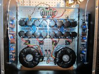
Yes, for sure. I see that the photos posted thus far were not clear in exactly which position on the sinks the boards and MOSFETs were mounted using spacers. I will post additional photos later today. I could have simply mounted the boards horizontally on the sink at a higher level, supporting them from below. But as pointed out by ZM, I wanted to keep them on the lower third of the sink, which is why I abandoned the horizontal position.
Nice build
This will be around 85W @8ohm amp (voltagewise). If you want it to stay in class A all the way, you wil need 1.15A pr device with 2 pairs. With +/-40V rails, that comes to 46W dissipation pr device. and a total of 184W pr ch. that might make the amp a little to hot. and the Lifetime of the outputs a little to short.
Hi. My intent has always been to bias to tolerable temperature. One of the reasons for building this was I and 6L6 were curious as to how high a bias could be achieved using the 5U sinks without a fan. That is, how high in life, rather than by calculations. I was shooting for 0.8 to 1 A without a fan, but hoping for more with crossed fingers. I'm not particularly concerned about leaving class A during peaks based on the very tiny bump on the distortion curve during the switch, especially with the large cap banks for each channel. (I just learned in the last few days of NP's article on leaving class A.) From my very limited understanding, classical music CDs are not as compressed and have a wider dB range (don't know that I am wording it correctly). Thus I wanted something to handle a moderately increased output and was counting on the caps handling the peaks. But I anticipate my comments may raise a rather vigorous discussion and corrections of my (mis)conceptions.
As the posts proceed, I'll post results of numerous measurements of distortion, clipping thresholds, waveforms, heat sink and device temperatures, etc. But you, indeed, are perceptive to recognize the heat issue. Another thing to be considered is that the electrostatics are supposed to average about 6 ohms. I don't think you will be surprised with the outcome. Please be patient with me as I work on getting these posts together in the evenings. More to come.
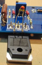
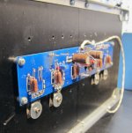
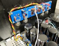
After soldering MOSFETs in place, I mounted thermistors. The board provides for mounting on both of the interior two MOSFETs (one N channel and one P channel), and allows two location options for each device. I used the holes closest to the edge of the board. In the first photo, I have simply soldered a single lead on the MOSFET and then placed the thermistor in place for the photo. Thermistors were pulled through and then bent over to lie on top of the MOSFETs.
I had mounted spade connectors on the amplifier boards for connections pertaining to power in and speakers out. For signal in, I used shielded twisted pair, with the ground connected to negative side at one end of the cable. While I wanted to use some very small spade connectors (and tabs) for signal in on the boards, I decided to solder the leads directly to the board to minimize the chance to pick up extraneous noise, though I don’t know this was essential. I then mounted the boards and MOSFETs, using mica and thermal paste on the transistors (had some arctic silver – not conductive). I confirmed lack of conductivity between any lead of a MOSFET and a non-anodized area of the the heat sink using an ohm meter. The M3 taps in the sinks worked perfectly.
I had mounted spade connectors on the amplifier boards for connections pertaining to power in and speakers out. For signal in, I used shielded twisted pair, with the ground connected to negative side at one end of the cable. While I wanted to use some very small spade connectors (and tabs) for signal in on the boards, I decided to solder the leads directly to the board to minimize the chance to pick up extraneous noise, though I don’t know this was essential. I then mounted the boards and MOSFETs, using mica and thermal paste on the transistors (had some arctic silver – not conductive). I confirmed lack of conductivity between any lead of a MOSFET and a non-anodized area of the the heat sink using an ohm meter. The M3 taps in the sinks worked perfectly.
Attachments
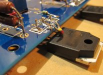
I meant to ask everyone whether they also would have soldered the shielded twisted pair input cable directly to the board or whether I would have done fine with a small spade and tab connector, instead. I have always soldered it directly to the board previously. Still, being able to easily disconnect input at the board could be convenient during repair/troubleshooting.
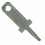
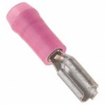
I had 2.79 mm wide male and female connectors I could have used. Digi-key A247TR-ND and WM18259-ND. Photos attached.
Thanks.
I had 2.79 mm wide male and female connectors I could have used. Digi-key A247TR-ND and WM18259-ND. Photos attached.
Thanks.
Attachments
I get mildly concerned about the JFETs becoming hot when the board is mounted in proximity to a hot heatsink. So I'd prefer the board at 90 deg to the heatsink, putting the input JFETs at a greater distance to the heat and in cooler air (hopefully). It might be a good idea to put heatsinks on the JFETs that are connected to each other, for better thermal tracking and cooler temps... JFETs move bias point nicely with temperature, iirc.
Of course, mounting off soldered connections only is going to create breaks in the solder eventually. So nobody reading should do that.
Nice clean looking build.
_-_-
I'd never use push on terminals for this application, others might, not me.
Of course, mounting off soldered connections only is going to create breaks in the solder eventually. So nobody reading should do that.
Nice clean looking build.
_-_-
I'd never use push on terminals for this application, others might, not me.
I get mildly concerned about the JFETs becoming hot when the board is mounted in proximity to a hot heatsink. So I'd prefer the board at 90 deg to the heatsink, putting the input JFETs at a greater distance to the heat and in cooler air (hopefully).
Interesting you mention that, Bear. I had wondered about the same thing. I'll take some temperature readings on the JFETs and on the sink and let you know how they compare. Thanks for bringing this up. As I recall, you have a set of these boards. Have you done anything with them yet?
Arctic silver is not conductive, but it is capacitative. Results for builders have been unpredictable in earlier builds, don't recall which one. I would exercise caution. The body/drain is connected to the output and the heatsink to ground, so you might have to deal with some additional stray capacitance on the output.
Arctic silver is not conductive, but it is capacitative. Results for builders have been unpredictable in earlier builds, don't recall which one. I would exercise caution. The body/drain is connected to the output and the heatsink to ground, so you might have to deal with some additional stray capacitance on the output.
Hi sangram. I would think that anything nonconductive would display a dielectric constant and create some sort of capacitance between the MOSFET and mica and/or heat sink. Are you stating that, for example, a non-conductive thermal transfer grease with different polarity (e.g., electronegativity) would be superior because of generating less capacitance? I've used this same tube of arctic silver on previous F5s without problems, and don't anticpate any with this build. And the anodized heat sink is really not conductive through the oxidized surface. I might have been able to get away without mica (I know some persons do this), but don't take such chances, myself. But your point is something I have never considered and that I know nothing about.
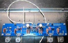
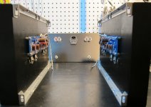
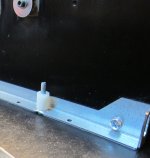
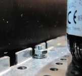
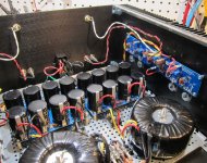
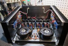
Assembly continued. As I mentioned earlier, I switched to ½ inch nylon spacers to elevate bottom panel. This allowed for plenty of room for the power run to the transformers. Also added washers to the hardware.
Attachments
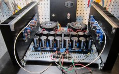
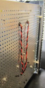
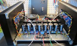
I used 16 gauge stranded for power, with red +, yellow ground, and black negative. On the amp boards, you can see where I had used a marker to mark out components that I would not be using. The perforated base plate was ideal for securing cables with cable ties. In the second photo, you can see where the 18 solid was used to connect grounds between halves of the PS boards at one end, as I mentioned earlier. The same thing was done at the other end of the PS board, as well. Then the back panel was attached and 16 gauge stranded took output from the boards to speaker terminals and attached with female connectors. The shielded twisted pair was soldered to input jacks. I significantly cut the resolution to these photos for posting.
Attachments
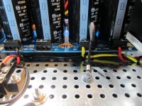
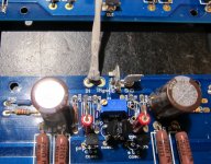
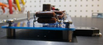
I hate to be to critical but, the pic below shows source Rs without enough space between each, or space from the board for proper cooling IMHO. These suckers get way hotter than you think and can cause catastrophic problems.
Also, the sharp bends, at the ends of the resistors were not formed properly. Stress from this practice will cause problems. A needle nose or round nose plier needs to be gripping the lead from the welded end and the bend should be from the other side of the plier, alleviating any stress from the welded lead. Or, use a lead forming jig
As far as board mounting, I like to use the spacers only on the opposite side from the xistors and let the xistors hold up the other side, after I mount everything and solder them
just my 2Cents
Attachments
Last edited:
Hi flg. Thanks for commenting. The leads from the top resistor were wrapped completely around the bottom resistor's leads before soldering and then clipping off the ends, though that may not be clear from the photo. But your point about keeping them cool is well-taken. I could/should have placed a space between the two resistors, perhaps. If I bias at 0.8 A, and then assume current as high as 3.2 A for periods of time (not just peaks), which would be extreme, that would be 2.56 W for each resistor, with each resistor rated at 5 W. And the great majority of the time the amplifier would be performing well below this. But still, your concern about temperature may be valid, especially with all the other sources of heat around. I'll add this to the temperature measurement list and report back. Thanks again.
What I was trying to say about the stress on the resistor is about damaging the contact from the lead to the resistor material itself. You could not have made a tighter closer bend to the body of that resistor. That lead connection has been stressed by the bending force. A lead forming tool allows for some space between the body of the resistor and your bend so that during bending there is no stress on the resistor itself, only the lead. The layout often does not account for the proper spacing to do this, which is common for power resistors. It is also way down there on the list of important things to make your build as "Hi-End" as possible. But, if it fails...
Re Rs: I have opened up dozens of amps to see resistors so brown you can't read the value and big burn marks on pcbs under them. 2 major variables are at work here aside from your Iq and years of heat. The lead of the R will carry some temp away to the board. But the overall size of the power R is most important to radiate that heat away. I see so many tiny little 1W size Rs rated at 5W Tolerating 5W at 150C is not my idea of a responsibly rated component. I typically use a power Rs rated 5X to 10X more than necessary to alleviate the temp issues somewhat.
Re Rs: I have opened up dozens of amps to see resistors so brown you can't read the value and big burn marks on pcbs under them. 2 major variables are at work here aside from your Iq and years of heat. The lead of the R will carry some temp away to the board. But the overall size of the power R is most important to radiate that heat away. I see so many tiny little 1W size Rs rated at 5W
Tolerating 5W at 150C is not my idea of a responsibly rated component. I typically use a power Rs rated 5X to 10X more than necessary to alleviate the temp issues somewhat. Those resistors are somewhat critical to the "sound" of the amp.
Compressit built up some F5s early on, and there was a rather dramatic change (for the better) when he went with (iirc) Caddocks for that position, and also the rating was (again iirc) with small heatsinks ~3-5x more than the spec'd wattage.
Hey flg, I'd not count on the Mosfets to hold the one side of the board. It will certainly work for quite a long time, but eventually those sorts of connections will end up stress cracking, even if it is those small micro cracks that make for intermittent. Generally speaking my feeling is that doing this is not "good practice".
But I agree completely about the need to move air around those resistors!
I'd pull them, and replace with redone resistors.
In production situations, I've seen ceramic spacers used to provide additional support on the leads when the resistor is raised off the board.
Agree 100% with flg on the over-rating of resistors.
_-_-
Well my theory regarding the mounting of the board on spacers of only one side is this; Heat related movement is going to happen. With the pcb mounted in 4 or more places, the xistors are being held by the solder on the board and the xistor fixing scheme, whatever that may be, forcing stress at this interface. I would expect less stress if a larger area were sharing that movement, such as with only the fixed transistor and the other side of the board being mounted. I also would hope the xistor mounting stays as originally fixed, allowing low thermal resistance to the sink without being pulled away by excess stress. The floating nature of mounting this way allows for movement without as much stress in any particular point.
- Status
- This old topic is closed. If you want to reopen this topic, contact a moderator using the "Report Post" button.
- Home
- Amplifiers
- Pass Labs
- F5c (cascode) cviller boards 40 V rails build