Dear, Sorscha, had receive a lot information from your post! Thanks! Can you help me too. I have AW250 Dual Mono (not dmb). I had fail to find schematics for it and use AW100 schematics. The history of the amp is unknown for me, but seems all the parts is original. The problem is that one Chanel dead and other play very weak.
one channel dead on the ampliwire 250
Hi all, I just stumbled over this thread. One channel of my ampliwire 250 just went dead when turning on the amp. Has somebody of you the schematics for the ampliwire 250? Or perhaps had somebody had the same failure? Thanks a lot for any help!
Hi all, I just stumbled over this thread. One channel of my ampliwire 250 just went dead when turning on the amp.
Has somebody of you the schematics for the ampliwire 250? Or perhaps had somebody had the same failure? Thanks a lot for any help!Hi, hifiboy;
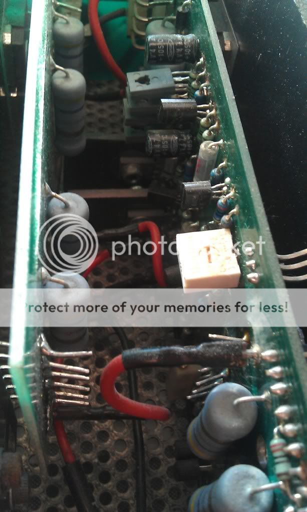
My AW 250DMB is in the mechanic right now, predictably suffering from the same failure. In my case, the problem is located in the left channel. After checking this side of the amp, I found three short-circuit transistors (reference: 2SC3281) plus the 12 W resistor just behind the on-off push button ([IMG=http://img440.imageshack.us/img440/702/igp7178.jpg][/IMG]). Right channel stays fine.
My AW 250DMB is in the mechanic right now, predictably suffering from the same failure. In my case, the problem is located in the left channel. After checking this side of the amp, I found three short-circuit transistors (reference: 2SC3281) plus the 12 W resistor just behind the on-off push button ([IMG=http://img440.imageshack.us/img440/702/igp7178.jpg][/IMG]). Right channel stays fine.
Hi Jorgitox, thanks a lot for the quick feedback! In my case the left channel is fine. The right channel relay which connects the output to the loudspeakers does not respond. I assume that the DC voltage exceeds the voltage in the mV range normally permitted for a push-pull. Why, I do not have a clue, but the power transistors may be shortened. need to measure this asap.What are the 2sc3281 transistors and the 12 w resistor used for? Are they driver transistors? Do you have an explanation for the failure?
I am not an expert on this subject, but this is not the very first faulty ELECTROCOMPANIET electronic I've owned. I thought this model had 6 output transistors for each channel, BUT the reality is that it owns 12 for each channel. This info shows how beasty this power amp is. The heat, time and way of use and electric peaks are examples for these failures.
This power amp have different types of transistors (once you check it all, just take each transitor's reference, that is showed clearly in one side of the transistor), so for you to know which one or ones is or are shortened, just make use of the oscilloscope. That's the only machine that can show you what's wrong.
Electrocompaniet make use of many transistors, maybe because of the high ampere output and high power of the unit even at 0,5 Ohms. I cannot explain for what is this resistor used for concretely. The only thing I know in my case is that must be changed because it is shortened like the three other transistors.
I am not able to make the job myself, but theorically I've learned a bit on these machines, and failures (when BIAS is not touched) are about blowing transistors and/or resistors.
Jorgitox, do you mean that the transistors fail due to wear out from thermal power voltage stress etc? Djk, that makes sense. But why should the driver circuit fail? I rather think it is doing its job of protecting the loudspeaker due to part of the rail voltage being connected to the signal out line due to a broken output transistor(s). ..?
The picture of the relay circuit is on ImageShack® - Online Photo and Video Hosting
The picture of the relay circuit is on ImageShack® - Online Photo and Video Hosting
It might be the relay itself. Either dead or worn out. In my Ampliwire one was completely dead. Since it had voltage across the coil, I figured the protection circuit was ok. The new relay did the trick.
If it clicks, you should open it and clean the relay conectors.
How old are yours? Whats the serial number? If its from the first 2-3 years, finding the correct schematics might be impossible. There are lots of slightly different versions, and it seems the paperwork got left behind.
Recap is also something to consider. 12mF 63v is rather easy to come by around here, and at a very nice price. The rest of the caps are $10 or so from any webshop.
One of the Roe caps was almost shorted in my left PSU, drawing enough current to fry the traces coming from the rectifier.
The 2sc3281 transistors are the actual output devices. 115v, 10A (100w Pt) from NEC. Very fast and designed for audio.
The 12W resistor is of no consern. If the amp powers up, the slow start is working fine.
C2681
You can run in to both 2681 and 3281 in Ampliwire.
Im starting to think its done on purpose.. just for kicks. They made sure no two amplifiers to leave the production line were identical.
Is it just that the proposed replacement is a bit of a stretch, or am I mistaken when I recall that the old NEC devices are quite different from the toshiba sc5200 ?
5200 in an Ampliwire.. it just doesn´t seem right. I know they are quite veratile, but still.
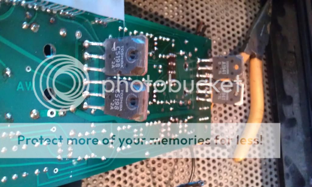
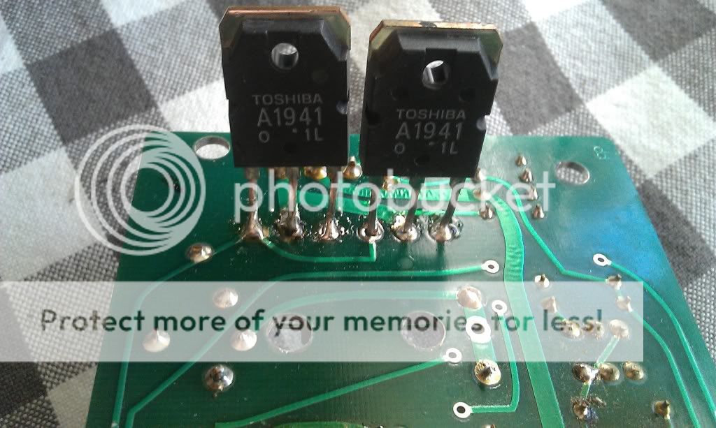
I just got one of these for free. One channel blown, the output devices in this channel were: Toshiba C5198/A1941. Other channel have Sanken C2837/A1186.
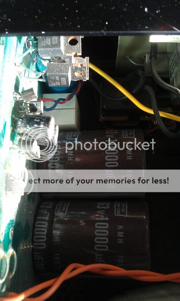
The problem channel had one ps capacitor nearly blown. Would a higher voltage or temperature rating help avoiding same problems later on? What would be a good choice for recapping, elna or nichicon?
A parts list would be highly appreciated(transistors).
The problem channel had one ps capacitor nearly blown. Would a higher voltage or temperature rating help avoiding same problems later on? What would be a good choice for recapping, elna or nichicon?
A parts list would be highly appreciated(transistors).
Hello Isak,
Littlediode is no problem and a good source. Perhaps a bit on the expensive side per piece, originals. I buy with them frequently, but solely for repair purposes. If you need a lot of parts in quantities, seek another option as it would be far too expensive.
Rebuild your power supply first. It doesn't matter much wich cans you take. I usually use either Philips or Roederstein (those you'll find in your aw 100)
A parts list isn't that easy as a couple of different units have been produced. Just post a detailed photo of your amplifier board. I can easily tell you what it is and send you information about it.
Cheers !
Last edited:

A very great issue is the contact quality of the connectors between the amp-PCB and the power supply PCB (often charred place in this area).
Very important are additional bypass caps behind the connection of the pos.-rail and negative rail on the amp PCB.
The ground wires must be soldered from the amp PCB and star ground on the power supply pcb.
Best solution is the replace of the connector poles through short cable wires.
Sound of this amp isn't good for me, as long as the genuine circuit topology is maintained. For me very bad engineering in most respects.
You will discover several hot spots (burned aeras) on the PCB, if this amp has been used intensively; also to observe often by Krell - go to
http://files.diyaudio.com/forums/gallery/data/500/medium/DSC00247_Large_.JPG
check also out this threads:
http://www.diyaudio.com/forums/soli...100-aw100-different-versions.html#post1913925
http://www.diyaudio.com/forums/soli...eone-clone-electrocompaniet-aw-amplifier.html
Last edited:
Yes I were planning to replace the circuit board connectors.
Are the original capacitors rated for 105 C? Seems there have been repairs done to both channels before. The bias adjustment is it counter clockwise on the upper pot?
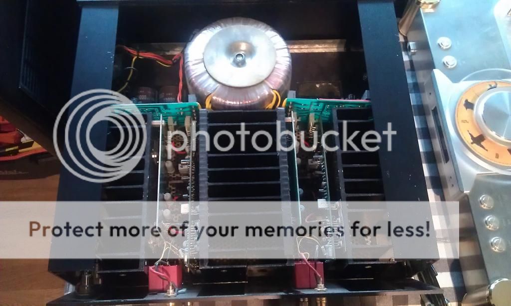
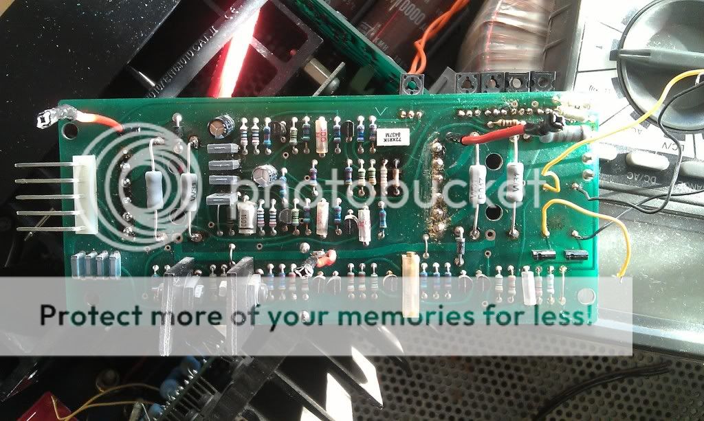
Here´s some new pics:
Are these the correct one´s, they are located on the working channel.
This is the channel with two open devices
These
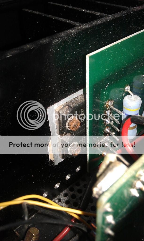
The rectifiers also differs, broken channel shown here
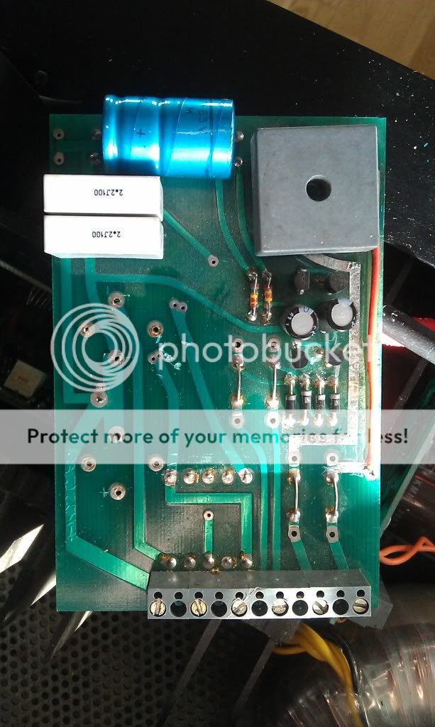
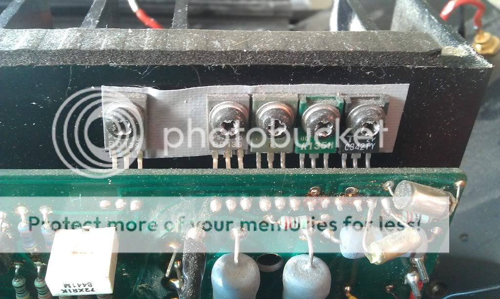
Here is the other one
Working channel
Prodused 25 June 1985 according to the stamp on one board.
Are the original capacitors rated for 105 C? Seems there have been repairs done to both channels before. The bias adjustment is it counter clockwise on the upper pot?
Here´s some new pics:
Are these the correct one´s, they are located on the working channel.
This is the channel with two open devices
These
The rectifiers also differs, broken channel shown here
Here is the other one
Working channel
Prodused 25 June 1985 according to the stamp on one board.
Last edited:
- Status
- This old topic is closed. If you want to reopen this topic, contact a moderator using the "Report Post" button.
- Home
- Amplifiers
- Solid State
- Electrocompaniet Ampliwire 100