Rollo,
depends on what you call class A, most of the produced class A amplifiers were not truly full class A biased.
Electrocompaniet used SK53 heatsinks for several of its 80s and 90s models. The 4 output devices on the heatsink of the AW-100 are capable of dissipating a total of a little over 50 watts max, that is good for running about 5 watts in class A.
To have the AW-100 in full class A the output stage would have to be capable of dissipating over 220 watts, times 2 for both channels. With the kind of output devices used on the early AW-100 model it would take about 5 of those heatsinks and some 16 output devices for each channel to handle that much heat. That's why true class A amplifiers are humongous.(huge monsters)
A set of 25 watt full class A amplifiers cost a whole lot more than the AW-100 in the mid 80s. The first Electrocompaniet model, the model 2, was 25 watts of full class A and had a 25% higher MSRP than the AW-100 in the late days of its existence. (about 70 watts dissipation per channel, for about $4750 in Europe in 1985, at the current $ exchange rate)
rollo:
I do believe R17 & 18 are 500 ohms - if memory serves me well
parallel 1K resistors were used - I will check over the weekend
since I placed the unit back in the rack.
jacco has a point regarding the power dissipation - I thought
the early AW25? were biased for class A - I emailed
T. Sandstrom and asked if he could provide clarification.
Check out the following links if you have not done so already:
www.wdehaan.demon.nl/various/sprintlayout/index.html
and
do a google search on the Otala Story
Also, I know this is rudimentary, but are you certain all the solder
connections are performing correctly? I recently repaired a
Tandberg 3001A FM tuner and found 12 bad solder
connections. Mostly around the terminal connections
that interfaced with adjacent boards. This took me much
time to locate all the bad connections, but the end result
was worth the time.
nuvo
rollo
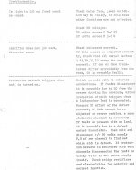
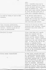
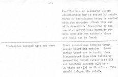
Attached is a troubleshooting list I located at the site of Terje Sandstrom - some good info - there are
three pics - I will try to attach all three if this site allows me - otherwise I will send one at a time
nuvo
P.S. If thermal runaway is indeed the source of the problem then use freeze spray - just a quick spurt -
on the device while measuring may help locate the suspected part. I may be wrong, but Q8 to Q11 seem
to be a long tailed pair with a current mirror as a load - if one transistor in the LTP is at fault you may get lucky and
locate the suspected part for further testing. Also, make sure Q8 to Q11 are mounted to the heat sinks firmly.
Hopefully, mica and heat sink compound was used - EC liked to use thermal blankets, I prefer using mica
with heat sink compound.
Attachments
Nuvo,
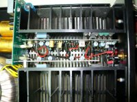
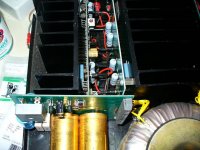
your picture has the same setup as the most powerfull EC model of the 80s, the AW250DMB. (including the SK53 heatsinks)
If that is 1 channel, i suppose your output stage has 4 pairs of output devices, 2 pairs on the main board and 2 on the auxiliary board mounted to the second heatsink ?
Does your model have regulated rails for the front ends, like the AW250?
jacco:
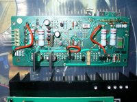
Thanks! You have a wealth of information on the EC units - and yes, there are 4 pairs of output transistors - two pair per board. The large (3 watt?) emitter resistors - one per transistor - show the approximate location.
I took another pic and hopefully it gives the perspective in relation to the power board. I have not studied the power supply in detail (no schematic), but I imagine the transistors mounted on the board may be there for regulation.
Also, I checked J1 for rollo and it is set at 0v - my meter (mv scale) showed 0.0009 to 0.0015 - meter tolerances to be considered - I put a scope lead on and measured less than 1mv ripple - good enough for me.
nuvo
Attachments
nuvo said:a wealth of information on the EC units
Not exactly, i had an AW65 for a while, likely the same version. Changed power amplifiers faster than underwear for a couple of years. I'm old enough to have had a peek-see inside different EC models at audio shows and retailer stores during years of fabrication.
Just curious if there had been an AW65 Sec. Ed., the AW65 was a real class A model.
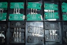
Apparantly EC turned the bias down in consecutive later higher power models, like with the AW100. After stepping up to the later editions with even fewer superfast Toshiba RET devices as shown below the bias went really down low, the schematic of the single pair output version on AndyPairo's homepage shows a bias setting for only 1/2 watt in A. I thought the AW65 to run very hot, having pairs of output devices side by side was not a very smart move. Placing 2 heatsinks that close to eachother makes life pretty much harder for the components in that gap.
Attachments
jacco
EC units are relatively rare here and you certainly have more information than I could find locally - I only know of two folks that ever owned one. Other than audiophiles, most people never heard of the company.
BTW - I need to make a correction to post # 28 - after some thought, the J1 measurements I posted seemed much too utopian so I rebalanced and measured again - J1 jumper reads 20.1mv for the left channel (8.4mv drop across the emitter resistors) and 17.9mv at J1 on the right channel (8.2 mv drop across the emitter resistors) - mea culpa.
nuvo
Hello Nuvo
back in town
in post #30 you say:
J1 jumper reads 20.1mv for the left channel (8.4mv drop across the emitter resistors) and 17.9mv at J1 on the right channel (8.2 mv drop across the emitter resistors)
I have to clarifications to ask hoping you remember:
1) I suppose you measured with JP1 in place, right ?
2) across the emitter resistors -->> means connecting the meter between R14 and R13 on the emitter side of Q8-Q9 ?
( because across emitter resistor R14 itself I read 9.86 Volts and across R18 8.18 Volts, which means about 21 mA through Q9 and Q11 emitters )
Thanks
Rollo") )
)
back in town
in post #30 you say:
J1 jumper reads 20.1mv for the left channel (8.4mv drop across the emitter resistors) and 17.9mv at J1 on the right channel (8.2 mv drop across the emitter resistors)
I have to clarifications to ask hoping you remember:
1) I suppose you measured with JP1 in place, right ?
2) across the emitter resistors -->> means connecting the meter between R14 and R13 on the emitter side of Q8-Q9 ?
( because across emitter resistor R14 itself I read 9.86 Volts and across R18 8.18 Volts, which means about 21 mA through Q9 and Q11 emitters )
Thanks
Rollo
)Aw100
Hello Rollo:
Hope your vacation was good. In answering your questions, yes jumper J1 was in place and the emitter resistors I measured were at the output (0.2R) which gave me about 40mA at idle. My amp is different fron yours, but the output transistors should correspond to your Q600 etc.
Also, the measurements you made at Q9 and so on appear to be in line with what I remember measuring on my amp. I do not have anything on the bench at the moment, but if you need specific measurements let me know and I will do it over the weekend.
One more thing - I noticed that the schematic you provided suggests dividing the amp to troubleshoot by lifting one leg of J1 and adding a 4700 ohm load resistor - apply a signal (I would use square wave) and study the waveforms - same technique to the second half - just remember to use a suitable high wattage 8 ohm resistor as a load.
nuvo
Thanks Nuvo for the offer, I'll take it )
Basically I wonder about the thermal drift of the Input stage for now.
I need to compare that behaviour of yours with mine, I don't know, maybe it is normal as is.
My JP1 is wildly moving from -12 Volts to 200mV ( set with pot R3 ) and subsequently slowly oscillating +- 3-400 mV.
If you could apply a scope on JP1 (and perhaps on output too) when amp is cold
and oberve the behaviour for a couple of minutes after power on.
It looks like a thermal feedback and yet I matched all the transistors (Q1-Q11) as much as possible.
BTW -- Do you know how the input stages are defined (Q1-Q11) ?
( I think 1st stage is Commom Emitter with common base load and gain 3.25, second stage Emitter follower gain 1, 3td stage Commom Emitter gain 2.28 )
Thanks again
Rollo
)Basically I wonder about the thermal drift of the Input stage for now.
I need to compare that behaviour of yours with mine, I don't know, maybe it is normal as is.
My JP1 is wildly moving from -12 Volts to 200mV ( set with pot R3 ) and subsequently slowly oscillating +- 3-400 mV.
If you could apply a scope on JP1 (and perhaps on output too) when amp is cold
and oberve the behaviour for a couple of minutes after power on.
It looks like a thermal feedback and yet I matched all the transistors (Q1-Q11) as much as possible.
BTW -- Do you know how the input stages are defined (Q1-Q11) ?
( I think 1st stage is Commom Emitter with common base load and gain 3.25, second stage Emitter follower gain 1, 3td stage Commom Emitter gain 2.28 )
Thanks again
Rollo
Rollo:
I measured J1 as requested - the waveforms at J1 just shows 3mV power supply ripple and slight noise on the output (via 8 ohm resistor). This was the case with the input shorted and non shorted. DC at J1 started at 42.88v and rose slightly to 43.26v after 20 minutes and held steady afterwards - the AC scale showed 0.003v after a 20 second sampling time (triplett true RMS DMM).
If your problems begin after warmup and you suspect a thermal problem then try using freeze spray (small controlled spurts) - my amp uses a 2SC2824-Y as a thermal current regulator and it was the source of my problems - the freeze spray also helped me isolate cracked solder joints - the ones you cannot see
on a visual inspection but plays havoc once things warm up. If that all fails then I would try isolating as indicated on the schematic and divide the problem between A1 & A2 and take it from there.
On the input stages- I stand to be corrected, but I would venture to say that Q1& Q2 make a long tailed pair, Q6 & Q7 emitter follower, and Q8-Q9 as a LTP and Q10-Q11current mirror as a load. See Rod Elliott at ESP audio for a good explanation on the LTP and current mirror circuits.
Hope this helps.
nuvo
Nuvo
you said:
DC at J1 started at 42.88v and rose slightly to 43.26v after 20 minutes and held steady afterwards -
I think you measured from -V isn't it ?
because before at JP1 you measured:
J1 jumper reads 20.1mv for the left channel (8.4mv drop across the emitter resistors) and 17.9mv at J1 on the right channel (8.2 mv drop across the emitter resistors)
Thanks
Rollo
Rollo:
I rechecked the voltage reading at J1 and I measured from -v and ground - both the same value. Give me a few days to find my past notes on the measurements in post # 30 so I can recollect what and where I was measuring. But in the mean time I reread your post # 34 and would like to comment that the wild swing at J1 (idle) is not normal - which led me to another thought - assuming the resistors on Q8-Q9-Q10-Q11 are within spec, have good solder connections and the transistors are good - then recheck the current mirror (Q10-Q11) to ensure that the mica/heat sink compound are in good condition and make sure the transistors are firmly secured to the heat sink itself. Current mirrors usually share the same heat sink since a difference in thermal emission will unbalance the current mirror and may cause you a problem.
nuvo
Rollo:
I had time today so I removed both PCB's and traced as close as possible to the schematic you provided and yes, I used the incorrect jumper (post 35 & 37) to make the measurement - my apologies for the confusion - unfortunately, my boards do not have the silkscreen legends so I need to trace the hard way. I located J1 and measured to what I believe is node 'DC' as illustrated on the schematic - on startup I measured 33.1mV (no ripple on the scope) - after 5 minutes read 26.5mV - after 15 minutes read 23.6mV - no fluxuations detected at all.
My previous mistake (post # 35 & 37) was that I believe I measured at node 'B' instead of J1 - which explains the ripple. My amp is similar to the schematic but does have differences - I do not have the servo protection circuit and I have dropping resistors in place of zeners - definitely an older version.
I will try to see if I can edit the photos I just took and place arrows to show where the measerements were located on my boards - not sure if I can size for this site but I'll give a try.
nuvo:
rollo
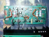
I labeled the attached photo - measured jumper J1 to DC and got the 35mV, etc readings posted previously. The transistor labels may be inverted since this was the best I could do with what I traced - in any event they should be paired correctly according to the schematic. Up at the top I labeled the thermal control
transistor (many circuits just use a diode) which was the original source of my problems.
Hope it helps.
nuvo
Attachments
- Status
- This old topic is closed. If you want to reopen this topic, contact a moderator using the "Report Post" button.
- Home
- Amplifiers
- Solid State
- Electrocompaniet Ampliwire 100