Hello guys I have an announcement to make I still have Dx Super A PCB but sadly the cost of shipping increased here in Puerto Rico to Europe $26.95 USD, only is less costly when I shipped to the USA territory usually is $5.95 USD depending on the USA address, so I decide to leave all to Brazilian boards Dx Super A because they are close to Europe so they can take care of that, and I will take orders for the USA territory.
Regards
Juan
Regards
Juan
Yes, white ones (now a day's are Black) from Zimmer
imap.eletro@gmail.com
Blue beauty ones are from Juan Vargas Diaz
regars,
Carlos")
imap.eletro@gmail.com
Blue beauty ones are from Juan Vargas Diaz
regars,
Carlos
Enjoy ...Blue or White, both are Dx Super A
Important video here;
https://www.youtube.com/watch?v=C31kX9YDstA
regards,
Carlos
Important video here;
https://www.youtube.com/watch?v=C31kX9YDstA
regards,
Carlos
Dx Super A video showing no power on thump
Here you have it:
https://www.youtube.com/watch?v=BKuRreRyC84
regards,
Carlos
Here you have it:
https://www.youtube.com/watch?v=BKuRreRyC84
regards,
Carlos
This unit has no power on switch...it has just a double input potentiometer
and a stereo switch that put 47uf non polarized capacitors in series with the speakers in order to listen voice only (news on TV)
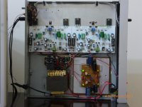
It is a Dx Super A, with decreased optimized bias of 90 miliamperes each rail, 25 plus 25 volts supplies, electronic filtering and Dx supply including error amplifier and series pass power transistors.... an unit optimized to lower power.
It is operating for more than 6 months..maybe one year, i am not sure...i was checking bias and output regulator voltage.... everything fine not needing adjustment.
It is connected to the satelite TV Receiver.
regards,
Carlos
and a stereo switch that put 47uf non polarized capacitors in series with the speakers in order to listen voice only (news on TV)
It is a Dx Super A, with decreased optimized bias of 90 miliamperes each rail, 25 plus 25 volts supplies, electronic filtering and Dx supply including error amplifier and series pass power transistors.... an unit optimized to lower power.
It is operating for more than 6 months..maybe one year, i am not sure...i was checking bias and output regulator voltage.... everything fine not needing adjustment.
It is connected to the satelite TV Receiver.
regards,
Carlos
Attachments
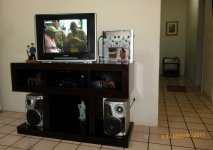
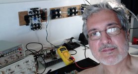
Here you see my reference unit, a Dx Super A with pcboard made by Juan Vargas Diaz
From "Coqui" pcboard Industries from Puerto Rico.
You see i am using it to compare to a Dx Class A (Pure)
regards,
Carlos
From "Coqui" pcboard Industries from Puerto Rico.
You see i am using it to compare to a Dx Class A (Pure)
regards,
Carlos
Attachments
Attachments

Most of the sound you listen is a leakage from living room ambience music
From Internet Radio - Miami - 256K
See waveform .... square wave from 10 to 40 Kilohertz
https://www.youtube.com/watch?v=VZp2bzbxRvQ
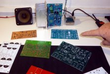
Juan Vatgas Diaz pcboards are very high quality ones
regards,
Carlos
From Internet Radio - Miami - 256K
See waveform .... square wave from 10 to 40 Kilohertz
https://www.youtube.com/watch?v=VZp2bzbxRvQ
Juan Vatgas Diaz pcboards are very high quality ones
regards,
Carlos
All right, gonna do it dear Juan.
But you can help me sending me your pcboard part list (bill o material including part numbers) this way i will check my own blue board and will put different values or modifications into a schematic.
So, send me your schematic with part numbers printed on it...also values you have.. and this gonna help me a lot.... not really needed BOM....just schematic with part numbers.
You know that i have one pcboard assembled, so, reference numbers (r2, c5, Q1 and so on) cannot be seen because components are covering these part numbers that helps people to insert parts only..after insertion the value is almost covered (cannot see) by the component itself.....gladly i have one pcboard not assembled..so..i can see reference values there.... and i can return you based on your own reference of part number.
I have several versions on my computer, to several voltages, several power levels and it is confused to me to be sure what kind of modifications was applied on this blue pcboard, the one you could see with very good square wave shape till 40 kilohertz.
carlos.eugenio1951@yahoo.com
nanabrother@hotmail.com
These are email adresses i use most often as you already know....it was posted to refresh your memory only.
regards,
Carlos
Attachments
Last edited:
This is really needed Juan...you are right to ask me that
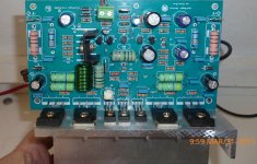
C13, the compensation capacitor is marked 150pf into blue pcboard silk screen.... real one i am using is 100pf.
Why?
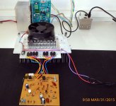
I do test watching the scope.... and i go reducing values till the amplifier oscilates, then i install one step up.
220pf, 180pf, 150pf, 120pf, 100pf, 82pf, 68pf, 56pf, 47pf, 33pf, 27pf, 22pf, 18pf, 12pf, 10pf, 5pf and 3pf... these are the values i have....so... first i install 220pf... then 180pf, then 150pf, then 120pf, then 100pf, then 82pf..... and oscilatted while using 82pf..then i install 100pf and produce a double check.
When needed value is small, i do use two steps up.
This is something i use to make real world..not simulator work, not calculator work...i do real life over a particular pcboard.... white ones from Zimmer cannot use 100pf...have to use 180pf....this depends on the pcboard design and parts used.
The real stuff is here..so..gonna copy all values to you in order you can update the schematic...much better....after receive some informations from you i gonna post and return you the schematic by email.
regards,
Carlos
C13, the compensation capacitor is marked 150pf into blue pcboard silk screen.... real one i am using is 100pf.
Why?
I do test watching the scope.... and i go reducing values till the amplifier oscilates, then i install one step up.
220pf, 180pf, 150pf, 120pf, 100pf, 82pf, 68pf, 56pf, 47pf, 33pf, 27pf, 22pf, 18pf, 12pf, 10pf, 5pf and 3pf... these are the values i have....so... first i install 220pf... then 180pf, then 150pf, then 120pf, then 100pf, then 82pf..... and oscilatted while using 82pf..then i install 100pf and produce a double check.
When needed value is small, i do use two steps up.
This is something i use to make real world..not simulator work, not calculator work...i do real life over a particular pcboard.... white ones from Zimmer cannot use 100pf...have to use 180pf....this depends on the pcboard design and parts used.
The real stuff is here..so..gonna copy all values to you in order you can update the schematic...much better....after receive some informations from you i gonna post and return you the schematic by email.
regards,
Carlos
 sometimes, sleep well brother
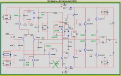
- Home
- Amplifiers
- Solid State
- Dx Blame ST together Dx Super A