the stand by current.
regards,
Carlos
ok standby current also
")
Regards
Juan
Here you have it playing Class A
500 mA per rail .... 25 + 25 volts supplies.
https://www.youtube.com/watch?v=CNhk8ta3Tp4
regards,
Carlos
500 mA per rail .... 25 + 25 volts supplies.
https://www.youtube.com/watch?v=CNhk8ta3Tp4
regards,
Carlos
Are you joking?
500mA of output bias allows a maximum of 1Apk for ClassA output current.
a +-25Vdc PSU probably allows a ClassAB output of around 20W to 25W
That 1Apk equates to <4W of ClassA
That means your amplifier is NOT a ClassA type.
It is a high bias ClassAB with added crossover distortion, due to non optimal ClassAB biasing.
This amplifier has change values ,resistors,capacitors,power supply, so many times.......Are you joking?
500mA of output bias allows a maximum of 1Apk for ClassA output current.
a +-25Vdc PSU probably allows a ClassAB output of around 20W to 25W
That 1Apk equates to <4W of ClassA
That means your amplifier is NOT a ClassA type.
It is a high bias ClassAB with added crossover distortion, due to non optimal ClassAB biasing.
This amplifier has change values ,resistors,capacitors,power supply, so many times.......
Yes Thimios,this is true DIY. Would you rather be spoon fed back to the Eico,Heathkit and Dynaco age? Even in that era there were modifications to the kits after production. Screw ups happen in DIY. That's the beauty. Enjoy life.....bring the Ouzo and let's break some plates!
Cheers
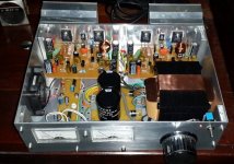
This big black unit is a Brazilian Quasar..but inside there's a Dx Super A
One tweeter is damaged...so, you can listen harshing treble.....just that.
https://www.youtube.com/watch?v=SQYtREgrcM8
This other video is a Dx Blame ST:
https://www.youtube.com/watch?v=zk4sYdf42rI
regards,
Carlos
One tweeter is damaged...so, you can listen harshing treble.....just that.
https://www.youtube.com/watch?v=SQYtREgrcM8
This other video is a Dx Blame ST:
https://www.youtube.com/watch?v=zk4sYdf42rI
regards,
Carlos
I have asked Eduardo Silveira a new recording because the one published
in the previous post was showing saturation in the recording or some problem in the mid range driver or tweeter...it is harshing...not perfect..and this amplifier does not sound this way.
regards,
Carlos
in the previous post was showing saturation in the recording or some problem in the mid range driver or tweeter...it is harshing...not perfect..and this amplifier does not sound this way.
regards,
Carlos
Attachments
in the previous post was showing saturation in the recording or some problem in the mid range driver or tweeter...it is harshing...not perfect..and this amplifier does not sound this way.
regards,
Carlos
REAL diy AMP!
TIME is not my friend lately , I"d like to make something like that housig you post!
Nice , regards,
Dear Cook77 and Vrystaat, the one build was not me, was Mr. Silveira
from Brazil..... he asked me to remove because he made bad recording and this will harm the brand as audio quality is not fine.
I will ask moderators to remove these videos and Mr. Silveira will make new ones soon....of course i gonna publish them here.
Was not me the builder..i am showing something a friend did with my amplifier circuit but i gonna search for the circuit he used to the meters...i suppose was some germanium diodes or silicon diodes as rectifiers.... some nanofarads as filters and a resistor...not more than that...but i will ask the guy the schematic to post here...the meter driver schematic.
Thank you all by the understanding..will ask moderator to remove these videos...was the video owner that asked me as he perceive it is a shame the audio quality in the recording..he gonna try to make it better..less level, more absortion material around...better light, flat recording without tone controls...well...he will manage to make better audio recording.
regards,
Carlos
what about mine? should i removed to ?
https://www.youtube.com/watch?v=_J55rQega2s&feature=youtu.be
https://www.youtube.com/watch?v=_J55rQega2s&feature=youtu.be
No!... post 1707 links only...or maybe the entire post...moderator will decide
Do not delete yours.... no reason for that dear Bagus.
I cannot see it Bagus.... it is blocked to my country due to copyright.
regards,
Carlos
Do not delete yours.... no reason for that dear Bagus.
I cannot see it Bagus.... it is blocked to my country due to copyright.
regards,
Carlos
Attachments

Last edited:
Sorry Bagus, not installing new stuff in my PC.... afraid of viruses
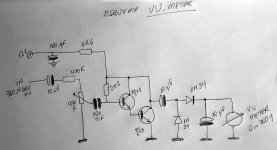
A friend asked me the VU Meter schematic.... so, dear Cook77 and Vrystaat.
Here you have it.
Capacitor in parallel with the meter will make it move more "average" like..gonna slow down the movement....may hold for a while.
regards,
Carlos
A friend asked me the VU Meter schematic.... so, dear Cook77 and Vrystaat.
Here you have it.
Capacitor in parallel with the meter will make it move more "average" like..gonna slow down the movement....may hold for a while.
regards,
Carlos
Attachments
Here you have a video about Eduardo Silveira...i have asked him to make a new video
Because the first one had bad audio recording...harshing sound.
But i am afraid you will not listen the audio..... he used a song that may be blocked...he know nothing about Youtube regulation and international laws.
This amplifier you see, the enclosure and pre amplifier is a Brazilian Quasar made from 1980 to 1988...inside there are Dx Super A modules and also a Dx Supply.... original Quasar pré amplifier is beeing used.... TL071 based circuits...tone control and filters.
regards,
Carlos
https://www.youtube.com/watch?v=cS-Hth9X5DE
Last edited:
I just did the 180 ohm swap for R4... I will say this was a solid amp to begin with and I am not sure how to describe the effect I would say less tiring, more transparent...maybe vocals are a little more transparent.
I am running this in a TO-3 version with MJ15015/6 at pretty high idle current. Still one of my favorite amps.
I am running this in a TO-3 version with MJ15015/6 at pretty high idle current. Still one of my favorite amps.
and this my 2nd e63 recording with 180ohm R
https://www.youtube.com/watch?v=tetejYTVo3k&feature=youtu.be
https://www.youtube.com/watch?v=Vehkp44GOoU&feature=youtu.be
https://www.youtube.com/watch?v=tetejYTVo3k&feature=youtu.be
https://www.youtube.com/watch?v=Vehkp44GOoU&feature=youtu.be
- Home
- Amplifiers
- Solid State
- Dx Blame ST together Dx Super A