I don't know if a different pcb needed for this low voltage modified Super A.
What you say Carlos?
Hi Thimios,
Pcb size is smaller,more compact (only one output pair and no Super A circuit) so enclosure can be more streamlined . Other than that,you are right,probably can use old board and modify.
Regards
I see the new pcb on post 1634Hi Thimios,
Pcb size is smaller,more compact (only one output pair and no Super A circuit) so enclosure can be more streamlined . Other than that,you are right,probably can use old board and modify.
Regards
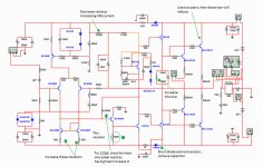
I was tweaking and i have found we need two pairs to reduce distortion
I could not reduce below 0.002% without the second pair.
So, a good idea is not to reduce pcboard size to let room to the second transistor pair.
You can perceive the sound, in special in the treble range.... resolution, audio becomes more defined.... if you listen to claps it will not sound alike rain falling in metalic ceiling.... sound of a bell become more clear.
I have not tested...this is just a simulation... real world can be different due to different specifications of components and tollerances of values.
At simulator, all parts are optimized and precise...you do not have NPN gain different than PNP gain.
regards,
Carlos
Attachments
Not exactly Junior35, first of all you have to reduce....
The input level when operating with 20 volts (compared to 25 volts) because this modification in power supply voltage makes your amplifier more sensitive and will need less input voltage to reach the threshold of clipping.... of course you can understand in the opposite way..it clips sooner, while you advance the volume control, you will need less signal to drive the unit into the clipping.... in this case we cannot call exactly as sensitivity...or we can.... it is more sensitive to destroy the sound clipping...less signal clips...so, it is a little bit philosophic stuff related the point of view....alike when the amplifier has not bass...maybe it has too much treble in the place to play less bass...got it?
So, to simulate you have to make adjustments... cannot just decrease voltage or increase, simulate and compare..this does not work fine..you have to optimize variables in each one of these two cases....input level and stand by current must be checked and readjusted if needed...to compare in the same conditions...to simulate under the same preset sittuation.... level into the threshold of clipping and stand by bias (no signal current to each one of the output transistors) must be readjusted.
Also you have to feed 40 mA to each one of the power transistors adjusting bias trimpot.... and to check reducing it and increasing it to each particular model of power transistor you may use to simulate...in some transistors you need 30 mA, in other you need 80 mA.... so...you have to simulate fourier analysis under several current presets.
Even this way, with 20V distortion increased in 0.000004% .... this is nothing, but to answer your question i have to be precise...yes, the distortion increased...no one can perceive, even meters have problem to measure, this means nothing...but to be precise:
Yes, it increases!
But i do not think, this kind of damage (0.000004% increasing) will not make the sun get out from the orbit, earth will not suddenly stop and then start to turn counter clockwise, also our planet will not tremble or shake.... earth angle will also not drift....so....this is not a tragedy.")
regards,
Carlos
The input level when operating with 20 volts (compared to 25 volts) because this modification in power supply voltage makes your amplifier more sensitive and will need less input voltage to reach the threshold of clipping.... of course you can understand in the opposite way..it clips sooner, while you advance the volume control, you will need less signal to drive the unit into the clipping.... in this case we cannot call exactly as sensitivity...or we can.... it is more sensitive to destroy the sound clipping...less signal clips...so, it is a little bit philosophic stuff related the point of view....alike when the amplifier has not bass...maybe it has too much treble in the place to play less bass...got it?
So, to simulate you have to make adjustments... cannot just decrease voltage or increase, simulate and compare..this does not work fine..you have to optimize variables in each one of these two cases....input level and stand by current must be checked and readjusted if needed...to compare in the same conditions...to simulate under the same preset sittuation.... level into the threshold of clipping and stand by bias (no signal current to each one of the output transistors) must be readjusted.
Also you have to feed 40 mA to each one of the power transistors adjusting bias trimpot.... and to check reducing it and increasing it to each particular model of power transistor you may use to simulate...in some transistors you need 30 mA, in other you need 80 mA.... so...you have to simulate fourier analysis under several current presets.
Even this way, with 20V distortion increased in 0.000004% .... this is nothing, but to answer your question i have to be precise...yes, the distortion increased...no one can perceive, even meters have problem to measure, this means nothing...but to be precise:
Yes, it increases!
But i do not think, this kind of damage (0.000004% increasing) will not make the sun get out from the orbit, earth will not suddenly stop and then start to turn counter clockwise, also our planet will not tremble or shake.... earth angle will also not drift....so....this is not a tragedy.
regards,
Carlos
Last edited:
The best audio recording ever made with a Dx amplifier model
Is this one.
Cranck your volume up (if you are using a Dx Amplifier)...others you cranck to 75 percent.
https://www.youtube.com/watch?v=nhrZAOABcHM
regards,
Carlos
Is this one.
Cranck your volume up (if you are using a Dx Amplifier)...others you cranck to 75 percent.
https://www.youtube.com/watch?v=nhrZAOABcHM
regards,
Carlos
Last edited:
The input level when operating with 20 volts (compared to 25 volts) because this modification in power supply voltage makes your amplifier more sensitive and will need less input voltage to reach the threshold of clipping.... of course you can understand in the opposite way..it clips sooner, while you advance the volume control, you will need less signal to drive the unit into the clipping.... in this case we cannot call exactly as sensitivity...or we can.... it is more sensitive to destroy the sound clipping...less signal clips...so, it is a little bit philosophic stuff related the point of view....alike when the amplifier has not bass...maybe it has too much treble in the place to play less bass...got it?
So, to simulate you have to make adjustments... cannot just decrease voltage or increase, simulate and compare..this does not work fine..you have to optimize variables in each one of these two cases....input level and stand by current must be checked and readjusted if needed...to compare in the same conditions...to simulate under the same preset sittuation.... level into the threshold of clipping and stand by bias (no signal current to each one of the output transistors) must be readjusted.
Also you have to feed 40 mA to each one of the power transistors adjusting bias trimpot.... and to check reducing it and increasing it to each particular model of power transistor you may use to simulate...in some transistors you need 30 mA, in other you need 80 mA.... so...you have to simulate fourier analysis under several current presets.
Even this way, with 20V distortion increased in 0.000004% .... this is nothing, but to answer your question i have to be precise...yes, the distortion increased...no one can perceive, even meters have problem to measure, this means nothing...but to be precise:
Yes, it increases!
But i do not think, this kind of damage (0.000004% increasing) will not make the sun get out from the orbit, earth will not suddenly stop and then start to turn counter clockwise, also our planet will not tremble or shake.... earth angle will also not drift....so....this is not a tragedy.
regards,
Carlos
Hi Carlos,
In post #1573 you did simulation for 20 volt supplies,but with one pair of outputs. Since that time you have suggested different component values/changes/removals. I'm not an electronic engineer. No oscilloscope,just simple tools. Do you mind to do some simulations for two output pairs with 20 volt supplies? I have Juan's DX Super A boards and BOM. My aim is to convert standard DX Super A to low voltage version. I don't care if distortion number has 4 zero's or 24 zero's. Just perceived sound is important. I understand that I will need to tweak some values for real-life amplifier,but if you can post suggested schema that would be great.
Thanks
uncle in e63 high frequency distort a lot. what you hear from the record is far from you heard a live. not like n8 (nokia you use) its clean. sub include. perfect for me.
hajame
i use 20k for 2 rail. thats 10k per rail i assume. and with no regulated voltage. dont worry this amp steady as a rock.. man... your set up is excellent. i'm sure you will satisfied with this one.
hajame
i use 20k for 2 rail. thats 10k per rail i assume. and with no regulated voltage. dont worry this amp steady as a rock.. man... your set up is excellent. i'm sure you will satisfied with this one.
Last diagram posted is good fro 20V and 25V
Let me say something to you dear friend.
Simulation is simulation and nothing more than a simulation...as i use to say, everything while simulating is optimized.. fake optimized results..... something you may not achieve in real life or may achieve... matter of luck.....real life, usually is another stuff....tollerances can change the performance a lot....your particular transistor used...the one you bought, can produce better results than the simulation i have made or can produce worse results...only God can tell you...i cannot.
It is very possible you achieve great results...better than you can achieve with competition...but numbers cannot be guaranteed.
One thing is simulation...other thing is real life.
I do think it is enough from simulations...last schematic provided is the one.
regards,
Carlos
Last edited:
If you want perfection in amplification, then do not waste your time
Go to the Dx Super A or any Blameless style amplifier (Dr. Self).
In this thread you have schematic, pcboard layout and all you need to assemble by yourself.....Juan may have some pcboards left if you do not want to etch them by yourself.
Olinda is a historical town, an ancient town, one of the first Brazilian towns built by Portuguese..it is nearby Recife, Province of Pernambuco...picture show you a landscape
regards,
Carlos
Attachments

Last edited:
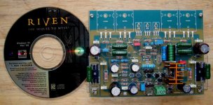
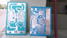
Home etched pcboard.
Sadly i have not the builder's name..... a pity, i am not that organized.
But, considering the cement colour, the type of construction the wiper holder (broomstick) and the ceiling, i can say this was made in South or Central America.
We can see Banana tree too...this is Central or South America, for sure.
regards,
Carlos
Attachments
Last edited:
well its my last project. bass from super a
https://www.youtube.com/watch?v=lcUt17MWQlE&feature=youtu.be
bye all its a nice to meet you.
and thank you for everything. God bless you
https://www.youtube.com/watch?v=lcUt17MWQlE&feature=youtu.be
bye all its a nice to meet you.
and thank you for everything. God bless you
You are welcome Bagus
Nice video....i love to watch videos...this is what i use to do all my free time...today watching WWI Airplane Manufacture....made of wood....nice!
Nice sound...it looks the speaker is too much powerfull compared to the power amplifier....it seems not moving the diafragm the way WE want.
What i mean..... too much stiff suspension... speaker made to receive much more watts compared to the power amplifier power delivery...not soft to move considering the power you are sending to the speaker coil.... well.... this is imagination....maybe i am wrong.
regards,
Carlos
Last edited:


 merry CHRISTmass to you all
- Home
- Amplifiers
- Solid State
- Dx Blame ST together Dx Super A