I hoped someone would know the origin of the Diamond name, or when used first
...difficult..
The Sansui Patent is from 1980, but there they did not call it diamond.
On the other hand for the buffer config I found an application note from 1989 by National, where the buffer config is called diamond - though this is no proof that the name was used for this config first.
http://www.ti.com.cn/cn/lit/an/snaa004/snaa004.pdf
Sorry guys, I did not want to spoil the thread with a long discussion about the name.
...diamonds everywhere...
Last but not least, I think also differential configuration which posted is old, not my invention, most likely also not Krell, most likely also not Linear Technologies with their LT1711...
Most likely Scott Wurcer's signature is simply true.

apexaudio
Sorry for another stupid question.
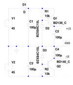
Can I use psu like bellow (sorry for D1) ?
Or better of is to load zener diode with some current and take the voltage from it ?
|Thanks
Yes, this is serial regulator and you can use it it's also capatience multiplier if you connect cap in parallel with zener. This regulator is better than only zener.
Regards
I have ordered some zeners. Next week I will try it.
But for now what we have is:
- I have changed feedback node for 10k/470R + 100pF cap
- increased vas emiter resistors to 47R to keep DC parameters more stable
- I think that vas compensation caps can be removed with similar config, te amp is bit slower (around 35V/us) but is rock stable with capactive load.
The overshoot is gone, I found that close to clipp square is a bit not symetric, I found that behavior with mje340/350 VAS pair in different amp too, after replacing them with eg toshiba driver tranies - all perfect (I will test that later on)
Now the amp is playing some acoustics alchemy on my founteks fr89ex and must say that top and middle frequences are extrodinary good. I do not know if this is good complain but looks like there is too much details in sound (some like some may not like)
Thanks Mile.
Attachments
I have ordered some zeners. Next week I will try it.
But for now what we have is:
- I have changed feedback node for 10k/470R + 100pF cap
- increased vas emiter resistors to 47R to keep DC parameters more stable
- I think that vas compensation caps can be removed with similar config, te amp is bit slower (around 35V/us) but is rock stable with capactive load.
The overshoot is gone, I found that close to clipp square is a bit not symetric, I found that behavior with mje340/350 VAS pair in different amp too, after replacing them with eg toshiba driver tranies - all perfect (I will test that later on)
Now the amp is playing some acoustics alchemy on my founteks fr89ex and must say that top and middle frequences are extrodinary good. I do not know if this is good complain but looks like there is too much details in sound (some like some may not like)
Thanks Mile.
Thank you, it's your amp I just give you idea to made it .
This topology is made for high definition amps and named HD.
Next upgrade will be cascode in vas.
Regards
apex
If I have to learn I will learn from the best.
thx
Can you post your prototype schematic with this measurement?
- increased vas emiter resistors to 47R to keep DC parameters more stable
It will change nothing if the voltage across the VAS emitters
resistance is not increased as well , you ll still have the same
delta with temperature variation , the thing is to increase this
voltage such that the VAS VBE variation ,2mV/°C , is rendered
less influencial.
As an axemple , if VAS emitter voltage is 0.2V the variation
will be 1%/°C , raise this voltage to let say 0.6V and variation
will be reduced by a 3 factor , wich will reduce accordingly
the VAS current variation.
This can be done either with slightly higher input stage current
or by increasing the input stage collectors resistances , or
a combination of both.
wahab
thanks for explaining! It is important that I will learn how to build the amp properly.
So basicly it is recommended to move the transistor ''working'' point to more ''open'' side as I understand (higher emiter voltage and higher emiter resistor value). In my case there is 1,2V acros the vas emiter resistor - would that be ok or increase more that voltage ? The vas bias looks stable at the moment.
Another silly question I have, what is the diffrence if base of VAS transistor is ''drinking'' the current from higher or lower resistor value of differential amplifier (470R in my case)?
I know how to set currents OK but above I am not sure so prefer to ask. Thanks
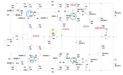
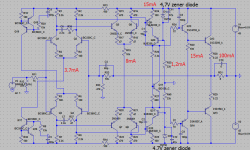
Bellow the schematic of measured amp.
It is bit overcompensated, the yellow cap can be bit lower (68pF), the green caps can be 22pF (i think),blue caps - looks like that they have to remain the same.
thanks for explaining! It is important that I will learn how to build the amp properly.
So basicly it is recommended to move the transistor ''working'' point to more ''open'' side as I understand (higher emiter voltage and higher emiter resistor value). In my case there is 1,2V acros the vas emiter resistor - would that be ok or increase more that voltage ? The vas bias looks stable at the moment.
Another silly question I have, what is the diffrence if base of VAS transistor is ''drinking'' the current from higher or lower resistor value of differential amplifier (470R in my case)?
I know how to set currents OK but above I am not sure so prefer to ask. Thanks
Bellow the schematic of measured amp.
It is bit overcompensated, the yellow cap can be bit lower (68pF), the green caps can be 22pF (i think),blue caps - looks like that they have to remain the same.
Attachments
Last edited:
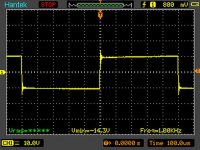
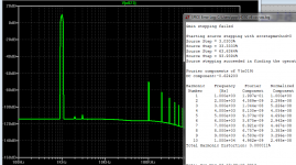
Something seems not quite right with the pics, or the test, or the output load used for the test.... The overshoot is gone, I found that close to clipp square is a bit not symetric...
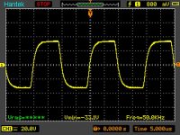
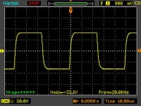
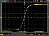
At 1 KHz in the 3rd pic, also labeled 10V/division, reading -14V.3 min, there is visible overshoot about 4V, with some ringing (probably would be more visible on expanded time scale, or if the freqency is increased to 10KHz from 1 KHz). 4V overshoot on a 10V signal peak (if real and not an artifact of the test), is a lot.
That suggests that (depending on speakers) higher audio frequencies would sound brittle at low-medium volume.
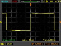
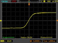
Then, last pic, at 20V/division, reading -35.6V min, no overshoot, but square wave shows signs of power supply being loaded, or some capacitance in the circuit becoming dominant. In other words, something is different.
You would expect your better behavior at the lower pk-to-pk voltage. 14V pk corresponds to about 12W power into 8 ohm load. A more realistic listening level than 35V pk (75W).
Perhaps I am not reading the pics correctly?
PMI
The 1kHz with overshot is 8R + 0,47uF in parallel, no inductor on the end of the amp.
With resistive load there is no overshoot at all, at all amplitudes square is clean.
The last pic is the 1kHz with 8R only, there is visible small disproportion in hight of square but this is my generator at lower frequencies is giving signal like that.
Ok, I get the issue w. the signal generator, but the rest seems wrong, somehow, I just don't know enough to guess at a reason. I've been lurking here, and reading, and your work looks great.PMI
The 1kHz with overshot is 8R + 0,47uF in parallel, no inductor on the end of the amp.
With resistive load there is no overshoot at all, at all amplitudes square is clean.
The last pic is the 1kHz with 8R only, there is visible small disproportion in hight of square but this is my generator at lower frequencies is giving signal like that.

I am guessing the test is being affected by something else.
Here is a test I ran recently, with very old test equipment....
50KHz square wave, 7.5R||0.2uF load
Second pic, 20V pk-to-pk, no Zobel, and no inductor on the output.
My slew rate measures higher, but at 1KHz, that will make no difference.
If the overshoot is an artifact of something else, and you are adjusting component values based on that result, you may be fixing a problem that does not exist...

The vssa amp is a lot faster amp and behaves really ok, but I was getting with it overshoot too with 0.47uF in parallel with resistor (even bigger overshoot, config -->renesas latfets + 22pf in drivers).
My equipmnet heh, generator from ebay (pwm based) and handheld scope, I wish to have somethink better but I have to work with what I have.
Next step is as mr Mile advised stabilised psu for front end, next prapobly cascaded vas (here I may need some help).
My equipmnet heh, generator from ebay (pwm based) and handheld scope, I wish to have somethink better but I have to work with what I have.
Next step is as mr Mile advised stabilised psu for front end, next prapobly cascaded vas (here I may need some help).
I have the Renesas Latfets, yes. The test in the post I linked was with 47pF compensation caps. Bigger resistors on the gates of the 2sk1058 (130r) and 2sj162(100R), than what you see on other versions of VSSA.The vssa amp is a lot faster amp and behaves really ok, but I was getting with it overshoot too with 0.47uF in parallel with resistor (even bigger overshoot, config -->renesas latfets + 22pf in drivers). ...
Later this week I will test with 22pF. I do not think I need to make the compensation caps that low for good audio performance though. I will post what I find.
I can make all kinds of overshoot and ringing happen, but when I clean up my usual rat's nest of wires and leads, there is little or none. So it could be partly your wiring. Try to move the load and the wires leading to it around a bit next time, and see if the overshoot/ringing changes at all.
I use mostly test equipment which was "retired" for one reason or another. Most of it is working fine, but calling it "used", may be a compliment. The word "recycled" comes to mind...
PMI
Thanks, I will check my bench setup.
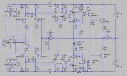
Tomorrow I will try vas in cascade in my prototype. I just do not know what kind of sonic advantage I can get from It. Schematic bellow. For now no regulated psu at front stage, I must get some parts first.
Thanks, I will check my bench setup.
Tomorrow I will try vas in cascade in my prototype. I just do not know what kind of sonic advantage I can get from It. Schematic bellow. For now no regulated psu at front stage, I must get some parts first.
Attachments
Last edited:
Can't say about the Cascode, sorry. Speaking of parts, have you tried other options besides the MJE340/350?PMI
Thanks, I will check my bench setup.
Tomorrow I will try vas in cascade in my prototype. I just do not know what kind of sonic advantage I can get from It. Schematic bellow. For now no regulated psu at front stage, I must get some parts first.
PMI
I didnt tryed other tranies there, I have a big bucket of mje with hfe around 200, so I decided to use them. I know that they are not perfect but first prototype is playing suprisingly good. Prapobly for voltages not over 45-50V BD139/140 pair would be good but there is a lot of better parts for this place.
I have incerased emiter resistors in first stage and amp is stable.
Attachments
PMI
I didnt tryed other tranies there, I have a big bucket of mje with hfe around 200, so I decided to use them. I know that they are not perfect but first prototype is playing suprisingly good. Prapobly for voltages not over 45-50V BD139/140 pair would be good but there is a lot of better parts for this place.
I have incerased emiter resistors in first stage and amp is stable.
Use BC550/560 instead MJE340/350 for Q9/10
- Status
- This old topic is closed. If you want to reopen this topic, contact a moderator using the "Report Post" button.
- Home
- Amplifiers
- Solid State
- Diamond Differential Amplifier