You can simple stabilised psu for front end just add zeners in parallel with C4 and C5 and recalculated resistors value.Next step is as mr Mile advised stabilised psu for front end, next prapobly cascaded vas (here I may need some help).
Very nice. For line level voltages when high gain transistors are available might get away without this level of complexity ? As an ongoing research SYMEF has been claimed to sound much better than LM3886 so far ") Thanks for posting.
Thanks for posting.
kind regards,
Harrison.
Thanks for posting.kind regards,
Harrison.
Keep on going this project.
My comment is just about the naming.
From my perspective this thread is showing only one schematic with a diamond topology and this was the Non Differential Elektor Diamond.
Attached a principal sketch of an input configuration which I would link to the title of thread.
Very nice. For line level voltages when high gain transistors are available might get away without this level of complexity ? As an ongoing research SYMEF has been claimed to sound much better than LM3886 so far
kind regards,
Harrison.
HD50 with +/-50V rail and 2 pair of outputs is without casscodes, but HD150 with +/-75V 4 pairs and HD300 with +/-95V rail and 6 pair of outputs must use cascode in diamond drive and vas.
Regards
I putted the cascade (added bc546/556 for now) and it looks ok so far. I have some work left to do anyway. Amp will be playing whole day at work.
I have putte 470R resistors in front 2 amplifiers (mayby bit too big value). Amp is bit slower but stable.
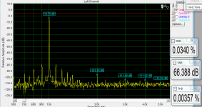
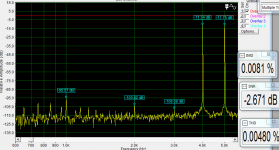
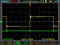
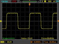
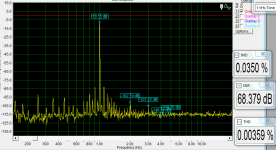
The overshoot at 1kHz at one of scope reading is with 0,47uF parallel with 8R.
apexaudio
I have few questions:
1. front stage - use the capactance multiplier psu + resistor as current source or better use ccs instead of resistor (with capactance multiplier psu) ?
2. second stage of differential amps - the max Uce voltage while clipping is around 28V (+/-45V psu) so I can use bc550/560 paris too ?
3. I am going to try fets in front stage - do I have to change a circuit a lot ? (in some amps I was just soldering j-fet instead od bjt and all looked ok)
thanks
I have putte 470R resistors in front 2 amplifiers (mayby bit too big value). Amp is bit slower but stable.
The overshoot at 1kHz at one of scope reading is with 0,47uF parallel with 8R.
apexaudio
I have few questions:
1. front stage - use the capactance multiplier psu + resistor as current source or better use ccs instead of resistor (with capactance multiplier psu) ?
2. second stage of differential amps - the max Uce voltage while clipping is around 28V (+/-45V psu) so I can use bc550/560 paris too ?
3. I am going to try fets in front stage - do I have to change a circuit a lot ? (in some amps I was just soldering j-fet instead od bjt and all looked ok)
thanks
Attachments
Last edited:
I putted the cascade (added bc546/556 for now) and it looks ok so far. I have some work left to do anyway. Amp will be playing whole day at work.
I have putte 470R resistors in front 2 amplifiers (mayby bit too big value). Amp is bit slower but stable.
The overshoot at 1kHz at one of scope reading is with 0,47uF parallel with 8R.
apexaudio
I have few questions:
1. front stage - use the capactance multiplier psu + resistor as current source or better use ccs instead of resistor (with capactance multiplier psu) ?
2. second stage of differential amps - the max Uce voltage while clipping is around 28V (+/-45V psu) so I can use bc550/560 paris too ?
3. I am going to try fets in front stage - do I have to change a circuit a lot ? (in some amps I was just soldering j-fet instead od bjt and all looked ok)
thanks
1. use ccs and zener + resistor or ccs as current source, post #68
2. second stage or diamond drive DD can use bc550/560, use hawksford cascode circuit from SR200 in vas for higher cliping level
3. use Sansui circuit for single n fet front end, post #54
Regards
Last edited:
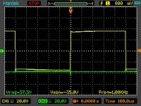
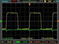
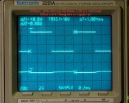
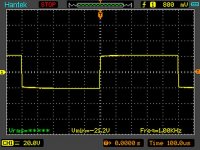
Is the green trace the negative supply voltage? If it is, where is the scope connected, close to the output transistors, close to the power supply...?...
The overshoot at 1kHz at one of scope reading is with 0,47uF parallel with 8R.
Those excursions on the green trace that I see are huge. They look like 10V pk-to-pk...PMI
The green supply voltage is connected after fuse and thin wire (maybe here is the bug). I have to prepare nice board and test again.
If those are real, whether on the ground bus or on the rails, it will affect the rest of your readings.With respect, I don't think so. I repeated one of my tests with a 6ft extra wire in the connection from the amplifier board to the positive supply terminal. Note the vertical scale of the second trace. That oscilloscope channel is set to 2V/division.PMI
The green supply voltage is connected after fuse and thin wire (maybe here is the bug). I have to prepare nice board and test again.
What you can see is the effect of a bit of added resistance from the wire, about 100~150 millivolts when power is drawn from that rail. No spikes or ringing on the supply at all, and I am not known for neatness when it comes to arranging test leads...
Attachments
PMI
I will have to check it. Thanks
I have both scope earths connected on the test resistor, I will connect them on the psu and test again. I have to prepare pcb.
I added 2*24V psu to the test board and resoldered a cap, now I toolks a bit better.
I will have to check it. Thanks
I have both scope earths connected on the test resistor, I will connect them on the psu and test again. I have to prepare pcb.
I added 2*24V psu to the test board and resoldered a cap, now I toolks a bit better.
Attachments
Last edited:
PMI
I will have to check it. Thanks
I have both scope earths connected on the test resistor, I will connect them on the psu and test again. I have to prepare pcb.
I added 2*24V psu to the test board and resoldered a cap, now I toolks a bit better.
What about sound, is there any change with this modifications?
Is there any decoupling caps in rail on your amp?
Regards
Last edited:
At the moment there are only two caps at 24V psu, there is no caps in 2nd and vas stage (I will make a proper board later on). I can not hear any diffrence with full psu and regulated psu at front stage (maybe at stereo and better speakesr there will be a diffrence).
The first version (no cascade and full supply at 1st stage ) was making bigger impression but I didnt measured thd to confirm if all is ok.
Overal sound is very detailed with good top presentation. With erthed input the amp is completly silent (im am testing burm and hiss sound with paper 2R speaker conneted).
Time to prepare a board.
Thanks apexaudio !!
At the moment there are only two caps at 24V psu, there is no caps in 2nd and vas stage (I will make a proper board later on). I can not hear any diffrence with full psu and regulated psu at front stage (maybe at stereo and better speakesr there will be a diffrence).
The first version (no cascade and full supply at 1st stage ) was making bigger impression but I didnt measured thd to confirm if all is ok.
Overal sound is very detailed with good top presentation. With erthed input the amp is completly silent (im am testing burm and hiss sound with paper 2R speaker conneted).
Time to prepare a board.
Thanks apexaudio !!
What about dc offset, are you add some circuit to set it or dc servo?
Last edited:
DC offset - i will put two resistors from +24 and -24V to potentiometer 5k, middle leg of pot to the feedback network. Is that ok ? I will post schematic evening time.
You can use my simple circuit for dc offset from post #71
Regards
Nice, good progress!...
I added 2*24V psu to the test board and resoldered a cap, now I toolks a bit better.

The amp is alive and was playing whole day (version with no VAS cascade).
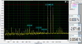
It sounds a bit differed to cascade one and has bit higher thd levels. There is measurable difference in intermodulation products levels and there is audiable difference in amp character.
The one with cascaded vas is very neutral in sound, very accurate hights, like sound just is flowing threw without any change.
The one with no cascade - it has its signature, there is more background sounds, the amount of details is bit higher (maybe only cause higher levels of harmonics products it can be heard like this).
Can someone advise me what about the spikes on psu rail ??
An externally hosted image should be here but it was not working when we last tested it.
An externally hosted image should be here but it was not working when we last tested it.
An externally hosted image should be here but it was not working when we last tested it.
An externally hosted image should be here but it was not working when we last tested it.
An externally hosted image should be here but it was not working when we last tested it.
Last edited:
The amp is alive and was playing whole day (version with no VAS cascade).
It sounds a bit differed to cascade one and has bit higher thd levels. There is measurable difference in intermodulation products levels and there is audiable difference in amp character.
The one with cascaded vas is very neutral in sound, very accurate hights, like sound just is flowing threw without any change.
The one with no cascade - it has its signature, there is more background sounds, the amount of details is bit higher (maybe only cause higher levels of harmonics products it can be heard like this).
Can someone advise me what about the spikes on psu rail ??
An externally hosted image should be here but it was not working when we last tested it.
An externally hosted image should be here but it was not working when we last tested it.
An externally hosted image should be here but it was not working when we last tested it.
An externally hosted image should be here but it was not working when we last tested it.
An externally hosted image should be here but it was not working when we last tested it.
I can't open pictures... can you post schematic of your psu, is there any 100nF caps in parallel with elkos?
apexaudio
There is problem in forum mechanism to upload the pictures, try just click on the links:
Zapodaj.Net - Darmowy hosting zdj?? i obrazków bez rejestracji! - 11c76ebfe5416.jpg
Zapodaj.Net - Darmowy hosting zdj?? i obrazków bez rejestracji! - 27d270b37f30b.png
Zapodaj.Net - Darmowy hosting zdj?? i obrazków bez rejestracji! - 720364ccafe4e.png
Zapodaj.Net - Darmowy hosting zdj?? i obrazków bez rejestracji! - 7cd8fe39de2a2.png
Zapodaj.Net - Darmowy hosting zdj?? i obrazków bez rejestracji! - 51cf2470127cc.jpg
and psu
Zapodaj.Net - Darmowy hosting zdj?? i obrazków bez rejestracji! - d366995459820.png
http://zapodaj.net/db5d7d35acd6c.png.html
The resistors between the big caps are 6x 1R each rail to separate charge currents of both caps sets.
My psu is ok I think (other amps are behaving ok on square full load), the voltage on the spikes is bootstrapped over the psu rail - the question is why ? (or my measure setup fault).
Under same condidtion different amp measured - psu voltage looks correct. I will measure current on emiter resistors tomorrow. The good think about amp is that with input grounded amp is dead silent.
Last edited:
- Status
- This old topic is closed. If you want to reopen this topic, contact a moderator using the "Report Post" button.
- Home
- Amplifiers
- Solid State
- Diamond Differential Amplifier