borys
I suggest first stage gain 100X and diamond drive gain 20X, you set gain 10X in both stages. Replace resistors R1,2,6,7,13,14,15,16 with 22R instead 220R and 47R and you have suggested gains in both stages.
Your pcb design is very nice, can you share it.
Regards
I suggest first stage gain 100X and diamond drive gain 20X, you set gain 10X in both stages. Replace resistors R1,2,6,7,13,14,15,16 with 22R instead 220R and 47R and you have suggested gains in both stages.
Your pcb design is very nice, can you share it.
Regards
Last edited:
")

The one with cascaded vas is very neutral in sound, very accurate hights, like sound just is flowing threw without any change.
The one with no cascade - it has its signature, there is more background sounds, the amount of details is bit higher
I prefer amps neutral in sound and speakers with signature T line is my favorite speakers.
Attachments
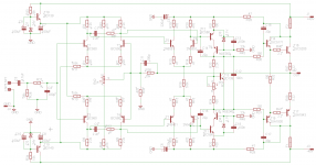
I have changed gain to x100 and x20 but I am getting very bad results (somethink I am doing wrong). Basicly with high gain at front stage there is very difficult to stabilise the circuit.
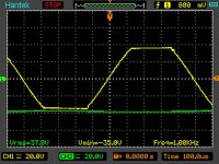
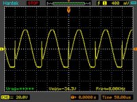
Another think is - clipping at higher than 4k frequencies, there are spikes present on sine and very high current spikes. Thats a pitty cause amp is playing really nice.
What is interesting, the spikes are present on symulation too. But version with cascaded vas hasnt got that problem. So I will prepare board with cascaded vas.
Attachments
Last edited:
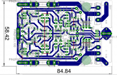
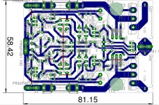
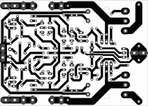
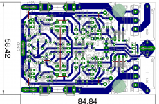
The new layout is ready, but I had to make a board bigger.
Nice pcb design, thanks.
Thanks
John
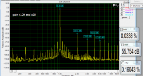
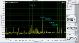
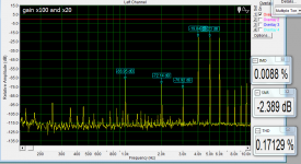
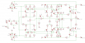
I have putted standard hawksword cascode. The schematic is bellow, but I have to test it further to match correct ''real life'' values of resistors. The first measy prototype was made with exacly same schematic as bellow (very good thd imd measurements and neutral sound). With too much gain in first two stages there is very hard (for me) to get the amp 100% stable in all aspects.Without rc network in first stage there is 3,4MHz small amplitude oscyllation on output etc etc .
John
I have putted standard hawksword cascode. The schematic is bellow, but I have to test it further to match correct ''real life'' values of resistors. The first measy prototype was made with exacly same schematic as bellow (very good thd imd measurements and neutral sound). With too much gain in first two stages there is very hard (for me) to get the amp 100% stable in all aspects.Without rc network in first stage there is 3,4MHz small amplitude oscyllation on output etc etc .
Attachments
borys,
T11/12 are up-side down in eagle sch...you may try to connect (after correction) 5V1 zeners at the junction of T11 emitter and lower end of R21 (T12 emitter and higher end of R22). Adjust value of R21/R22 so you have say 10mA for Tr and 2-5mA for zeners (or two green leds in series and bypass both with one 100nF film cap).
T11/12 are up-side down in eagle sch...you may try to connect (after correction) 5V1 zeners at the junction of T11 emitter and lower end of R21 (T12 emitter and higher end of R22). Adjust value of R21/R22 so you have say 10mA for Tr and 2-5mA for zeners (or two green leds in series and bypass both with one 100nF film cap).
borys,
T11/12 are up-side down in eagle sch...you may try to connect (after correction) 5V1 zeners at the junction of T11 emitter and lower end of R21 (T12 emitter and higher end of R22). Adjust value of R21/R22 so you have say 10mA for Tr and 2-5mA for zeners (or two green leds in series and bypass both with one 100nF film cap).
Thanks
Ofcourse there is mystake there thanks!! I will correct that later on.
I have changed gain to x100 and x20 but I am getting very bad results (somethink I am doing wrong). Basicly with high gain at front stage there is very difficult to stabilise the circuit.
Another think is - clipping at higher than 4k frequencies, there are spikes present on sine and very high current spikes. Thats a pitty cause amp is playing really nice.
What is interesting, the spikes are present on symulation too. But version with cascaded vas hasnt got that problem. So I will prepare board with cascaded vas.
My mistake about suggested gain, on my last schematic it's 56X in 1 stage and 5,6X in DD but not tested.
apexaudio
I have checked:
x50 - front stage
x20 - second stage
- VAS - single transistor
Above configuration was stable, no oscilations but clipping above 4k with sine (with square was ok) was very bad.
The enhanced cascode has had better performance on measurements so I am going to test it on monday. Bellow corrected test board an schematic (gains will be checked at real amp to get best performance).
Attachments
apexaudio
I have checked:
x50 - front stage
x20 - second stage
- VAS - single transistor
Above configuration was stable, no oscilations but clipping above 4k with sine (with square was ok) was very bad.
The enhanced cascode has had better performance on measurements so I am going to test it on monday. Bellow corrected test board an schematic (gains will be checked at real amp to get best performance).
Check X5 second stage
borys,
An 5V1 zener has a much larger noise compared to 2 x green LEDs in series...if you choose to keep zeners as voltage references you have to filter noise with an electrolytic cap say >10uf and up. You may also try to discard C17/18 and lower value of R29/30 base stoppers to something like 22-68R if you exchange R36=39k, R39=1k2 C11=22-33p...sim it see what's happening. Also, your DC offset correction is not good, see link for inspiration http://www.solaris.no/electronics/power_amp/ampzilla/ampzilla2b.gif
An 5V1 zener has a much larger noise compared to 2 x green LEDs in series...if you choose to keep zeners as voltage references you have to filter noise with an electrolytic cap say >10uf and up. You may also try to discard C17/18 and lower value of R29/30 base stoppers to something like 22-68R if you exchange R36=39k, R39=1k2 C11=22-33p...sim it see what's happening. Also, your DC offset correction is not good, see link for inspiration http://www.solaris.no/electronics/power_amp/ampzilla/ampzilla2b.gif
The Sansui Patent is from 1980, but there they did not call it diamond.
That was probably the Sansui marketing department who called it so, the name appears here in 1979 :
Ralisation d'un amplificateur classe A de 20W
Historically interesting, in the same article, there is the schematics of one of the first CFA of the word, the Hiraga's class A power amp, which input circuit configuration is now known as "diamond".
- Status
- This old topic is closed. If you want to reopen this topic, contact a moderator using the "Report Post" button.
- Home
- Amplifiers
- Solid State
- Diamond Differential Amplifier