I'd forgotten you were using a preassembled board... it was many hundreds of posts ago 
As long as the little SMD transistor turns fully on then there is no problem. You can check that easily by measuring the DC voltage across the collector and emitter. When the relay is on there should be less than 0.1 volts across C and E.
You don't need add any more resistance, just connect the gate output to the 10k. It can not draw more than around 0.5milliamps on a 5 volt supply so no problem.
If you need a lower resistor (because the transistor isn't turning on fully) then just tag it onto the base of the transistor directly (use a wire) and then wire to the gate.
Running a bicolour LED should be no problem although the final arrangement will depend on whether its common anode or cathode.
That's an easy check to make on the transistor, and I'll remove the 330 Ohm. Adding a resistor across would be the creating a parallel resistor.
But why would the 5V from the AND gate be different than the 5v currently supplied? The AND is not outputting 5V as a trigger?
Just Googled on the led types, indeed it is depending on the connection to make to the relay.
But why would the 5V from the AND gate be different than the 5v currently supplied? The AND is not outputting 5V as a trigger?
Just Googled on the led types, indeed it is depending on the connection to make to the relay.
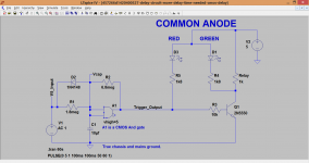
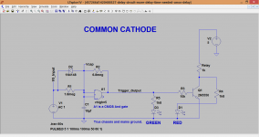
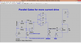
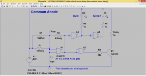
Here are the two circuits you need for the LED depending which type it is. The third diagram shows how to parallel the unused gates to use as a buffer to get more current drive. I would recommend that if driving LED's as well.
The output voltage from a single gate will fall under load, that's normal. Paralleling the gates will help stop that. Alter the LED resistors to get the brightness you want.
The output voltage from a single gate will fall under load, that's normal. Paralleling the gates will help stop that. Alter the LED resistors to get the brightness you want.
Attachments
Hello Mooly,
Thanks, really learning a lot with these schemes. Needed some time to figure out the common anode version, but I understand that you are using the 0 of the AND trigger as GND for the Red Led.
I tested my led and it is a common cathode version.
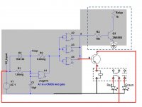
In the meanwhile I also drew a scheme (Just PowerPoint…). I have attached it. I used in my version a separate relay to switch between green and red. One trigger is send to the existing relay on the separate board (in the dotted area) and the same trigger to the additional “LED relay”. Updated it with the high current version of the AND gate.
Thanks, really learning a lot with these schemes. Needed some time to figure out the common anode version, but I understand that you are using the 0 of the AND trigger as GND for the Red Led.
I tested my led and it is a common cathode version.
In the meanwhile I also drew a scheme (Just PowerPoint…
). I have attached it. I used in my version a separate relay to switch between green and red. One trigger is send to the existing relay on the separate board (in the dotted area) and the same trigger to the additional “LED relay”. Updated it with the high current version of the AND gate.Attachments
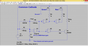
In the common anode version the red LED lights when the output of the AND gate is at logic zero. The gate sinks the LED current. The green LED is simply across the relay coil. When that is active the green LED lights.
The common cathode is similar but upside down and back to front. Now the red for off LED draws its tiny current through the relay coil (the current is so small it won't pull the relay in). When the relay is on the voltage across the transistor is essentially zero and so the red LED then goes out. The green LED does the opposite and is fed from the gate output.
Your circuit is a little scary
The input trigger signal doesn't correspond to the relay drive on a time scale... the whole point of the delay circuit... and so using that to light one of the LED's would be out of step with the relay. Also the trigger signal disappears when off and so the other LED wouldn't light because its 5 volts would have disappeared
Just looking at your circuit again... of course your driving the transistor from the delay output... so just the problem of you using the input trigger as the 5 volt supply for the transistor collector. And no LED limiting resistors... don't blow your LED up when you get it. Solder the limiting resistors to it first to save accidents.
Maybe some clarification needed from my side
- The delay time is mainly needed for the relay on the separate board, the LEDs are just indicators, so it not a problem when the timing is not exactly the same.
- It would be beneficial for me to have the LED's including control on a separate board and not integrated onto the main already existing board.
-The 5 Volts I used to drive the Red and Green Led is directly derived from the main power supply, so also the input of the AND circuit. The relay is switching it to the red or green led.
- I thought the trigger would behave like delay on and and stay on,
Just also reading your second reply, indeed I forgot the resistors before the LEDs
Do I understand correctly that I also have to add a resistor like R3 before the transistor?
I've assumed that the 5 volt trigger input isn't a supply but a switched input (such as from a microprocessor or a manual switch) that turns the relay on and off with the main 5 volt rail being a separate thing.
If you just want it to work when the 5 volt rail appears then you can couple those points together.
I think that is what you mean
So when the 5 volts appears the red LED is on, then when the relay changes the red one goes off and the green lights up. That should work There are a few ways of doing it all...
I'll have to leave it for tonight but running the LED's direct from the gate and relay would be the simplest solution. You only need connect wires to the relay coil points on your premade board for that.
If you just want it to work when the 5 volt rail appears then you can couple those points together.
I think that is what you mean
So when the 5 volts appears the red LED is on, then when the relay changes the red one goes off and the green lights up. That should work
There are a few ways of doing it all...I'll have to leave it for tonight but running the LED's direct from the gate and relay would be the simplest solution. You only need connect wires to the relay coil points on your premade board for that.
You usually expect to see a reverse diode across the relay to accommodate the current surge when the relay coil field collapses.
I'm assuming that's already taken care of. The relay and transistor is on a premade PCB that's all complete. I think there is a picture of it earlier in the thread somewhere.
indeed, that is what I mean
When the unit is powered on (220 V is switched) the 5 Volt becomes available.
With this rail 5 Volts the delay circuit is powered and the Leds are powered.
I have planned two relays in my scheme. The one already present on my main board and a second one controlling the leds. The second one and delay circuit to be fixed on a circuit board I'll have to make. Then I will connect it to the existing board.
I've planned to modify as less as possible on the already existing circuit board, but being able to add the delay and led control via an already available connector by means of a flat cable.
The diode is indeed in place on the existing board, however I will need to add it to the second relay I planned for the led's
Using a relay to drive the LED's is very messy and wasteful tbh. The voltage source V1 is now the supply with no separate trigger input.
If you replace the And gate with a Nand type (such as a 4011, its similar but it inverts) then you can run the LED's from the delay circuit directly.
If you replace the And gate with a Nand type (such as a 4011, its similar but it inverts) then you can run the LED's from the delay circuit directly.
Attachments
The relay driver transistor should be saturated when it is ON.
Saturated means:
Ic:Ib ~ 10:1 (there is quite a lot of leaway in the base : collector current ratio)
i.e. the base current into the transistor switch should be approximately 10% of the relay coil current.
You need to know the relay coil current.
A 5V relay is different from a 12Vrelay, it generally draws more current than a 12V and both generally draw more current than a 24V relay.
You can calculate the relay coil current from the resistance of the 5V relay coil. If the relay coil has a resistance of 120r, then it draws 5V/120r = 40mA
This would be the value you use to work out the required base current for the driver.
Tell us the relay current, or the relay resistance and we can show how to determine the base resistor value that determines the base current and then ensure that the driver is saturated.
Last edited:
Instead of mechanical relays maybe it would make more sense to use something like this? http://www.irf.com/product-info/datasheets/data/pvt312.pdf
Mike
Mike
I don't really understand why you've got the CMOS logic in there, better to use an opamp wired as a comparator... The whole circuit seems to me to be flaky, can't you come up with something a bit more conventional?
101 different ways and means. The design is repeatable and cheap. If you have an opamp design (or any other) then by all means post it and we'll take a look.
Normally I'd use a Microchip PIC for this... then once the relay has pulled in I can easily reduce the current with the addition of only a diode
You could cascade a couple of delays if you need a lot of time. Cap values as shown are pretty arbitrary. LM2902 has a pretty high input impedance, but you might want JFET input
You could cascade a couple of delays if you need a lot of time. Cap values as shown are pretty arbitrary. LM2902 has a pretty high input impedance, but you might want JFET input
An externally hosted image should be here but it was not working when we last tested it.
Looks like a case of out of control "project creep" to me. The OP's original query was how to increase the delay time on a simple and functional circuit. Now he's being steered into building something way more complex and costly than necessary. Why do we do this?
Mike
Well the goal posts moved for one thing with the introduction of status LED's
I stand by the CMOS variants as being a simple cost effective and workable solution. The parts cost tuppence and should be available anywhere.
- Status
- This old topic is closed. If you want to reopen this topic, contact a moderator using the "Report Post" button.
- Home
- Amplifiers
- Power Supplies
- Delay circuit, more delay time needed